Utilizing the services available from SendCutSend to help fabricate your parts means you’ll need to send us design files. You can use whatever software you prefer, whether that’s Autodesk, SolidWorks, or even Illustrator, but here we’re going to cover Fusion 360. You can find tutorials for other software in our blog.
There are four ways to export a DXF (Drawing Exchange Format) file from Fusion 360, and in this article we’ll show you the steps to do them. Of the four different methods, we recommend the first two, depending on whether you’re using Standard Components or Sheet Metal Components. The third and fourth methods are not recommended when using Fusion 360 to make parts for SendCutSend as they often produce undesirable geometry when preparing for the laser cutter. We’ve included them here in case you need to create a DXF for other purposes.
For even more detail, we have in depth guides to exporting a DXF from a sketch and exporting a DXF from the Flat Pattern Mode, covering the two workflows we recommend using when designing and ordering from SendCutSend.
How to Make a DXF File
Creating a DXF using Fusion 360 is a fairly easy process. If the geometry already exists, there’s little more to it than selecting what you want to export. If you don’t need to model a whole part, you can simply sketch the geometry you need and export a DXF right from there. The first method we’re going to cover here is exporting from a sketch. That sketch can be buried in an existing component, or you can create it from nothing for your DXF.
Before we get into the details, two things to keep in mind:
Tip #1: Regardless of which method you choose, always open your DXF in another Fusion 360 file or a graphics program to double-check the desired geometry is included.
Tip #2: Be sure to export your designs in either millimeters or inch units; we have guidance on how to change units in Fusion here.
How to Export a DXF in Fusion 360
Method #1 – Save As DXF from a Sketch
The easiest way to turn your non-sheet metal Fusion 360 designs into a DXF is to save the sketch as a DXF. In the Fusion 360 Browser, right-click on the sketch and select “Save As DXF.”
This method, however, will include only the geometry in that individual sketch. The sketch may include unnecessary geometry or not enough of the desired geometry. For best results, use the Project tool to include any geometry you would like to have in the DXF file.
Follow these steps to correctly export a sketch as a DXF:
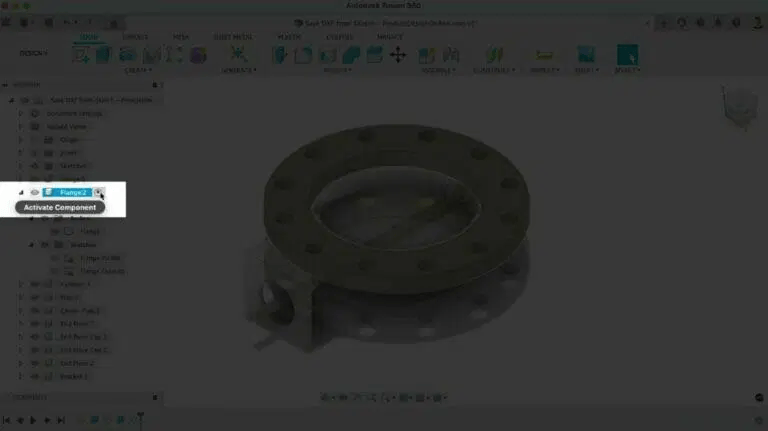
Step 1: Activate component
To place all desired geometry into a single sketch, start by making sure the desired component or sub-assembly is active. The active Component will determine where the sketch becomes nested.
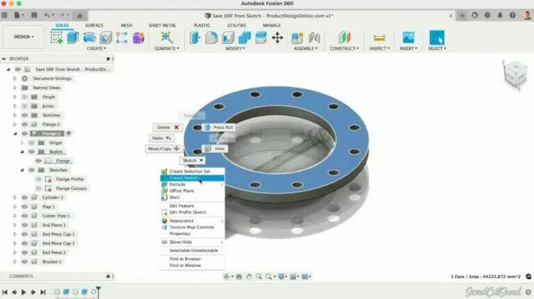
Step 2: Create a new sketch
Create a new sketch on an existing planar surface or by referencing a construction plane that’s parallel to the geometry.
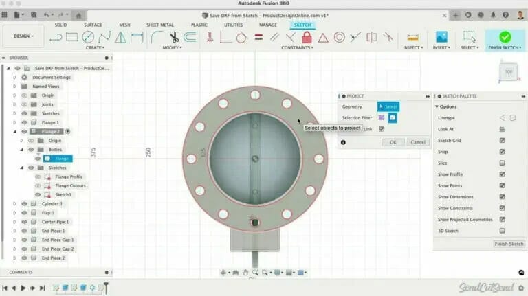
Step 3: Activate Project tool
Activate Project from the create menu of the Sketch tab or with the keyboard shortcut letter “P.”
Step 4: Project contours into sketch
Once active, use Specified Entities if you’d like to select specific parts to project into the active sketch plane. Otherwise, use the Bodies option to quickly project all contours.
Step 5: Select “Projection Link”
Although this doesn’t affect the DXF export, we recommend keeping the “Projection Link” option checked. This ensures the projected geometry automatically updates based on changes to the model, making it easy for you to save a new DXF with limited work.
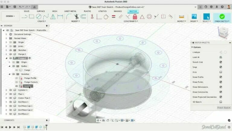
Step 6: Make sure geometry is purple
After clicking OK, you’ll see that the projected geometry is the color purple. Purple geometry helps you distinguish the sketch geometry driven by existing sketches or bodies.
Step 7: Select new sketch
In the Browser, right-click on this newly created Sketch that includes the desired geometry.
Step 8: Save as DXF
Select Save as DXF and define the desired file name and location.

Step 9: Double check file
Always open the DXF in a separate Fusion 360 file or a graphics program, such as Adobe Illustrator. Double-check that all desired geometry is included. Checking the file will help avoid sending unwanted geometry to the laser cutter.
In some scenarios, you may want to copy components or include additional parts in the DXF export. Place them side-by-side with Joints or Arrange commands. Laying them flat will allow you to Project all the geometry into a single sketch that you can Save as a DXF file.
Save As DXF from a Sketch is available on the following Fusion 360 license types:
| Personal Use (Hobbyist) | Education | Startup | Commercial (Paid) |
| Yes | Yes | Yes | Yes |
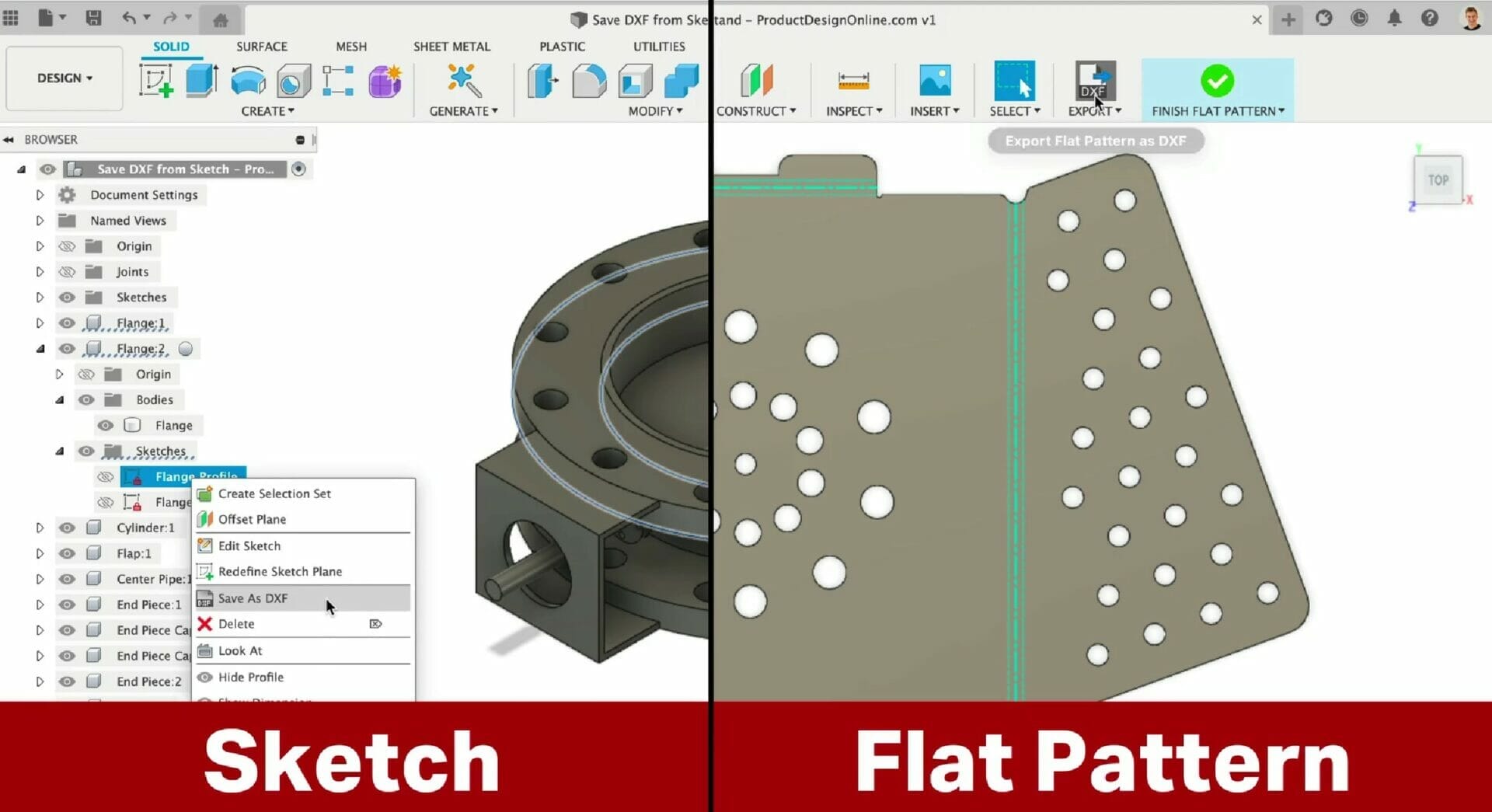
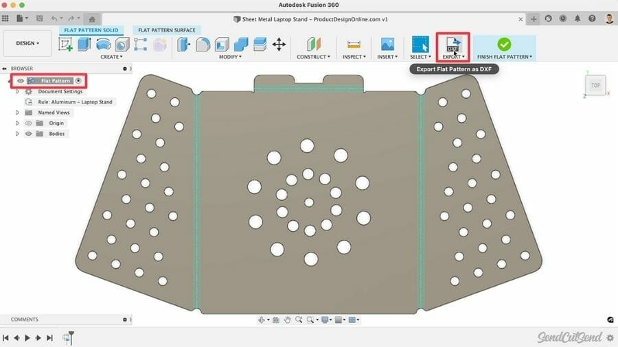
Method #2 – Export Flat Pattern as DXF
Exporting a DXF from Fusion 360’s Flat Pattern mode has some advantages and disadvantages when it comes to laser cutting. The DXF will include all outer profiles, interior profiles, bend center lines, bend extend lines, and any text, which will all be assigned to different layers within the DXF file. This is the second export workflow that we do recommend.
Follow these steps to correctly export a Flat Pattern as a DXF:
Step 1: Create Flat Pattern
Use “Create Flat Pattern” to initiate a new flat pattern. If you’ve already created a flat pattern, activate the Flat Pattern in the Fusion 360 Browser.
Step 2: Export Flat Pattern as DXF
You will then find “Export Flat Pattern as DXF” in the toolbar.
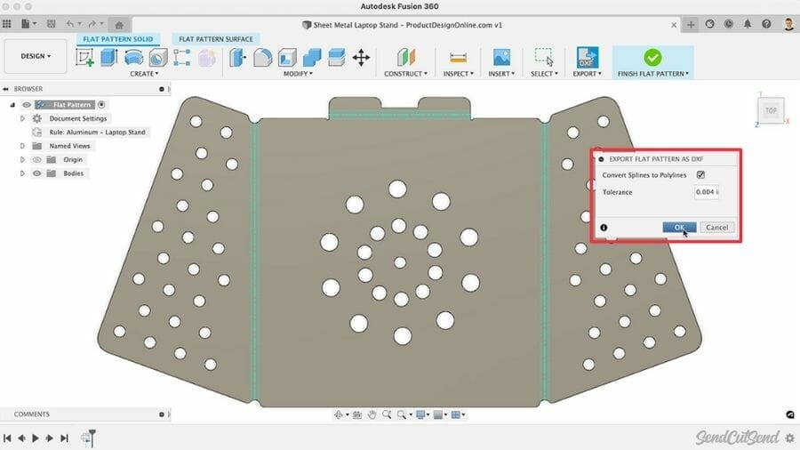
Step 3: Change splines to polylines
After selecting the export tool, check “Turn Splines to Polylines.” This will simplify the geometry and make it better for the laser cutter. You can leave the default tolerance of .004 inches.
Export Flat Pattern as DXF is available on the following Fusion 360 license types:
| Personal Use (Hobbyist) | Education | Startup | Commercial (Paid) |
| Yes | Yes | Yes | Yes |
Method #3 – Export Sheet as DXF
Below is a screen shot of exporting a sheet as a DXF, which we do not recommend.
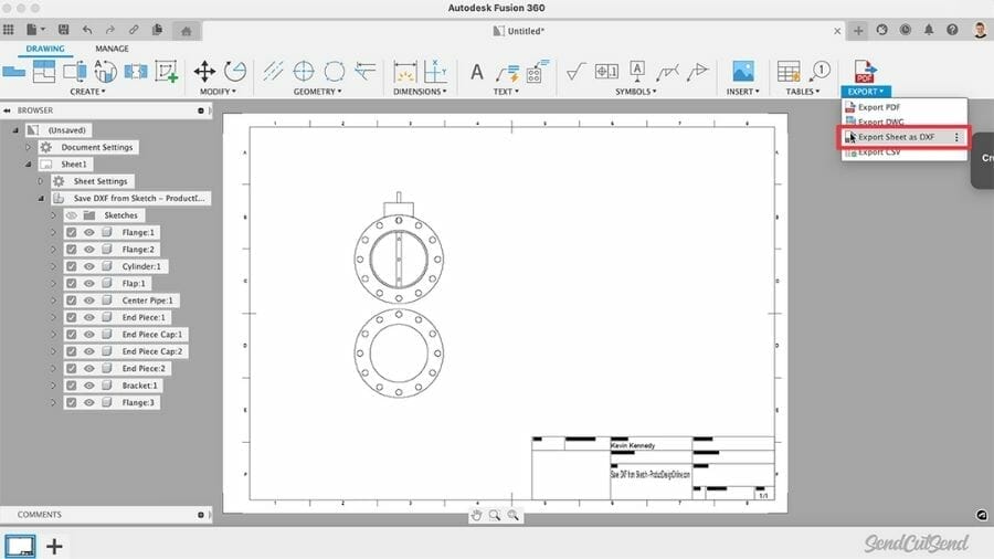
You will also find that you can save a DXF file from a 2D Manufacture drawing in Fusion 360’s Drawing Workspace.
However, keep in mind that this workflow will export to the scale of your drawing sheet, regardless of the size of your design file. The export will also include all the drawing elements in the DXF file, such as the title block. We cannot quote designs with files that include these elements.
Exporting from a 2D manufacture drawing is also not available via the free Personal Use license. For these reasons, we don’t recommend this workflow.
Export Sheet as DXF is available on the following Fusion 360 license types:
| Personal Use (Hobbyist) | Education | Startup | Commercial (Paid) |
| No | Yes | Yes | Yes |
Method # 4 – Export DXF from File Menu
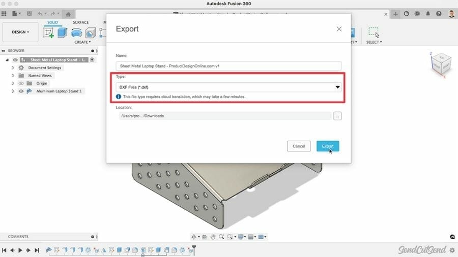
Lastly, you may discover that DXF is listed as an option from the File > Export menu. We recommend avoiding this fourth and final workflow as well. This DXF workflow uses cloud translation and will take a few minutes to process.
With most files, it will also create a 3-dimensional DXF file that includes all geometry in your design. This results in a complex DXF file with more geometry than necessary, often producing undesirable results when preparing for the laser cutter.
Important: Files exported from this option can not be uploaded to SendCutSend for quoting as it produces 3-dimensional DXF files that are not ready for a laser cutter.
Export DXF from File Menu is available on the following Fusion 360 license types:
| Personal Use (Hobbyist) | Education | Startup | Commercial (Paid) |
| Yes | Yes | Yes | Yes |
Exporting to DXF from Fusion 360: Video Tutorial
Reaping the Benefits of DXF Files For Your Projects
If you intend to use your DXF for laser cutting, the two recommended export workflows are exporting to a DXF from the Flat Pattern Mode for sheet metal components, and saving a sketch as a DXF from the Browser for non-sheet metal components. The other methods we discussed here can produce a DXF, but may cause issues when quoting or machining your parts. So we don’t recommend those for laser cutting.
Our goal is to help our customers get the most out of the services we offer, whether that’s CAD tutorials, simple guidelines, or answering Frequently Asked Questions.
If you have any other questions about utilizing Fusion 360 for your designs, check out our Fusion 360 tutorials or reach out to one of our design partners. If you’re interested in learning more about all the services we offer, check them out here. When you’re ready with your design, upload it and get an instant quote!