There are a lot of options when it comes to choosing which software you use to design your parts, ranging from 2D vector graphics programs to full 3D CAD modeling. One aspect of these software packages you should consider is whether they use Direct editing or Parametric editing. Keep reading to learn more about direct vs. parametric modeling, and the value each one brings to your project.
Parametric vs. Direct Modeling
Both methods offer you the flexibility to make changes to a product design, and are available in free software packages all the way up to the most expensive professional software. (Some software even offers both methods at the same time.) Both methods also start by sketching lines or simple shapes and building out from there. The difference between direct and parametric modeling is in the way you interact with the design.
What Is Parametric Modeling?
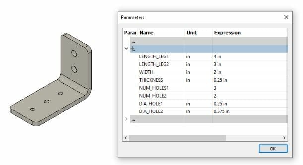
Parametric editing differs from direct editing in that its geometry is based on a set of parameters, or rather the relationships between your part dimensions and ratios. The geometry is based on a set of dimensions and relationships to other geometry (parallel, perpendicular, collinear, symmetric, horizontal, etc.). Those dimensions and relationships are kept with the design and can be modified. Need to make your part shorter? Change the dimension that controls the length.
Uses of Parametric Modeling
Parametric modeling is useful for building in the important dimensions and relationships of a design. A pattern of holes that are all the same size and evenly spaced are just a few mouse clicks to create with parametric modeling. Keeping features in the right locations even if other geometry around them is changed, can be easily accomplished with parametric modeling.
Parametric modeling allows for that design intent information to be captured. When you, or a team mate or maybe a customer revisit the design in the future, all those relationships are intact. Assuming they were created intelligently and correctly, that can be an extremely valuable addition to your design files.
Parametric modeling also allows for separate parts to share information. If two parts need to bolt together, the hole pattern sizes and spacing in one part can be driven from the other part. This ensures the parts will always interface correctly without having to change each individually with every design revision.
What Is Direct Modeling?
In simple terms, direct editing lets you interact with the geometry directly. You pick the geometry (a face, edge, vertex, etc.) and drag, push, pull, rotate to change the design. If needed, you can make these moves precisely by specifying distances, but those distances don’t get captured in the design to refer back to later. This is likely where a lot of beginners start because it can be the easiest to understand. It’s similar to interacting with a physical object. Need to make your part longer? Grab the end and pull it to where you need it.

Uses of Direct Modeling
Direct modeling can be useful early in a design, where the relationships between features may not be clear or known yet. It can also be useful in situations where changes are needed quickly to an existing component, but pre-existing feature relationships cause unwanted changes.
Caution should be used when using direct editing on existing designs, especially if you weren’t the original designer. With direct edits, there aren’t guardrails in place to prevent you from making a change that would cause problems. It’s completely up to you to check any related geometry and make the necessary changes. Good documentation can help whether you’re working by yourself and revisiting designs from the past or if you’re working with a team and sharing designs.
Pros and Cons of Direct vs. Parametric Modeling
There is no right or wrong choice when it comes to Direct vs Parametric modeling. Which one you choose can depend on how you intend to use your designs, what you’re designing, the time you plan to spend on your design, or simply which software you’re already familiar with.
Here are some reasons you may want to choose one over the other:
Advantages of Direct Modeling
Lower Learning Curve – Probably the biggest factor in why people choose a direct modeling approach is that it has a lower learning curve. Because modeling directly can be more intuitive for beginners, a lot of users start here. Modeling your design directly doesn’t require much forethought, you can just jump in and get your design started.
Speed (up-front) – Direct modeling can be quicker initially, when you’re first laying out your design. You’re just getting a rough shape, fine tuning details to get it the way you want, or when you’re just importing/modifying an existing shape like a logo or text. Direct modeling can be used to quickly brainstorm concepts because it has a more freeform method of interaction.
Organic Shapes – This one may be a little controversial in the Direct vs Parametric discussion. Some users believe free flowing shapes or more organic looking designs are easier to achieve using direct modeling techniques. This likely boils down to the specific application and user preference as even parametric tools can be used to drag splines and curves into whatever shapes the user desires.
Imported Geometry – Sometimes you need to import geometry or models you didn’t create. This is common for vendor parts that you incorporate into your design. Often vendors won’t want to provide a fully featured parametric model, so they provide a 3D CAD model that’s been stripped of all that information. When working with those models, direct modeling can make more sense, although parametric tools can still be used to create new features.
Direct modeling/editing is best suited for simple designs that aren’t likely to change much later, when working with preexisting shapes, or when working with more organic shapes.
Advantages of Parametric Modeling
Speed (future changes) – This is one of main reasons parametric software is so powerful and why it’s the method of choice for nearly all professional 3D CAD packages. A little bit of forethought to place dimensions and relations where they’ll be most useful can make future design iterations and changes much easier. This is especially true as your design gets more complex, where multiple parts interact with each other.
Captures Design Intent – Capturing design intent refers to creating features, placing dimensions and adding relations in ways that control the important aspects in your design. If it’s important to your design that a hole be located an exact distance from the left edge and centered between top and bottom edges, you can add the dimension, add the centered constraint and the hole will always be where you need it. If the edge moves, the hole moves with it. If the design gets taller, the hole stays centered.
Organization – Direct modeling allows you to interact with your design freely, but it can be easy to accidentally change something unintentionally. Feature-based designs are much more organized using parametric modeling. Each feature is captured in an organized feature tree. Each feature is controlled precisely by dimensions and constraints/relationships you’ve added. As your design grows and increases in complexity, that organization can be very helpful.

Better/More Modeling Tools – Typically, parametric modeling offers a much wider range of modeling tools to make creating your designs quicker and easier. A good CAD software will give you the right tools you need during the design process without making you come up with workflow workarounds to turn your ideas into models. Parametric type software is more common in engineering and manufacturing environments, and so it tends to get more and better tools developed for it. However that can come at a higher cost.
Parametric modeling/editing really shines as designs get more complex than just simple shapes or when a design may need to be changed later. It’s also the easiest way to create multiple versions of parts.
10 Best Software for Parametric and Direct Modeling
The software you use to create your design comes down to a lot of factors, and those won’t all be the same for everyone. Sometimes cost/availability is the primary driver, sometimes a specific feature. In this section, we’re focusing on which software uses Parametric Modeling and which uses Direct Modeling, so you can include that when making your decision.
In no particular order:
- Illustrator – 2D Direct
- Inkscape – 2D Direct
- SketchUp – 2D/3D Direct
- Blender – 2D/3D Direct, but addons exist to give Blender some Parametric capabilities
- Tinkercad – 3D Direct
- Fusion360 – 2D/3D Direct and Parametric
- FreeCAD – 2D/3D Parametric
- SolidWorks – 2D/3D Direct and Parametric
- CREO – 2D/3D Direct and Parametric
- OnShape – 2D/3D Direct and Parametric
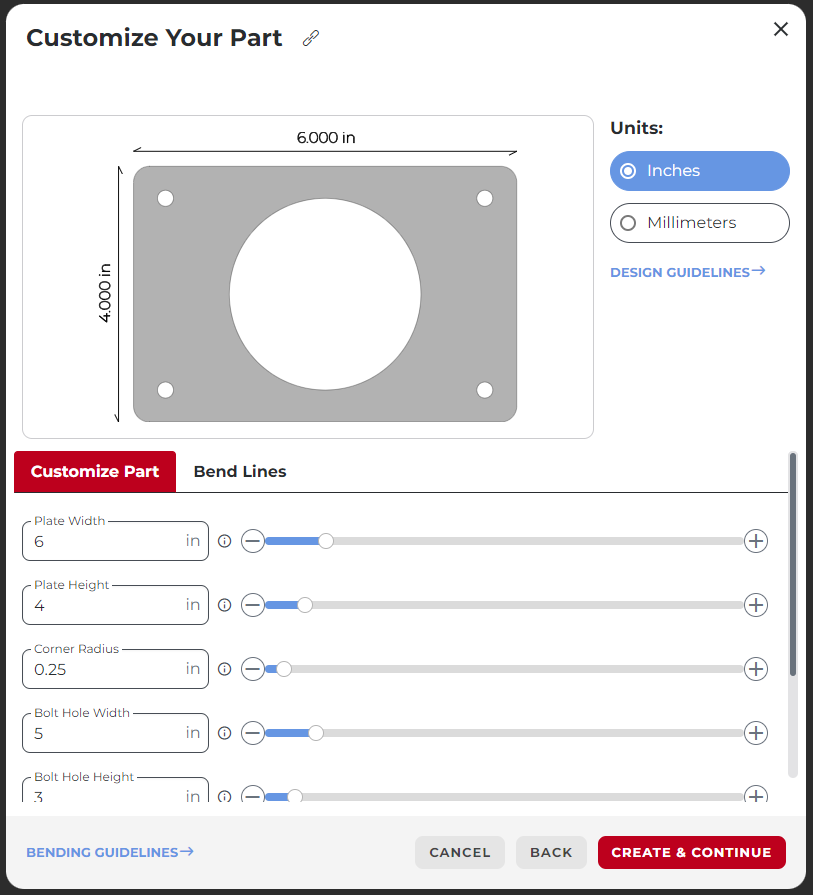
SendCutSend’s own Parts Builder is a 2D Parametric design tool. Sizes and quantities of features are controlled by user driven parameter values.
Which Should You Choose?
Direct modeling is best suited for simpler designs where you don’t expect to make many changes in the future. Or when you just need to experiment with the design and want that freeform experience like modeling with clay. Parametric modeling is better suited to designs with more complexity, or any design you expect to change. Parametric modeling offers a more organized/structured approach to creating your parts.
Just about any design can be created using either of the methods we’ve discussed here. Sometimes the best tool for the job is the one you already have or the one you already know how to use. But knowing the pros and cons of each makes it easier to pick.
If you have further questions about modeling in 2D or 3D CAD software for laser cutting, check out our blog with other helpful resources.