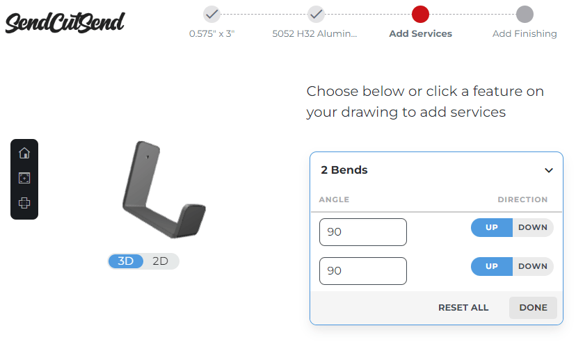
When you upload your bent files to SendCutSend’s website for instant pricing, you should be able to preview a model of your design in 3D to check the angles and flange orientations. You can click the 3D/2D toggle to switch between previews. When configuring bends, the 3D preview should show by default.
3D part preview troubleshooting
If your design is not previewing correctly in 3D after uploading to our website, there could be a couple of reasons.
1. Your design needs bend reliefs
Bend reliefs can help prevent bulging in the corners of your part and is required for a successful bend in some cases. Check out our blog post on designing bend reliefs to learn when to use bend reliefs and how to create them.
2. The bend line doesn’t extend the full width of the part
It’s important that the bend line you include in your design extends the full width of the part because it will otherwise be ignored by our automated processing. Our Guide to Configuring Bends In Our App can show you how to properly include bend lines in your design.
3. The file is not set up correctly
There are a few factors that play into a file not being set up correctly for bending.
Common Bend File Issues
- Incorrect bend line indicator
- for example, the ‘Hidden’ line style is selected in a DXF exported from SolidWorks or AutoCAD
- see our tutorial for how to avoid this in SolidWorks: How To Map Bend Lines into Layers and Linetypes in SolidWorks
- for example, the ‘Hidden’ line style is selected in a DXF exported from SolidWorks or AutoCAD
- Incomplete geometry (broken contours / disconnected paths)
- An open entities error can be due to stray geometry in a 2D file, or 3D STEP file setup issues
- Incorrect file type (for example, uploading a non-.ai file from Adobe Illustrator)
- STEP/STP format file contains a part that does not meet our guidelines
We have bend file setup tutorials for popular CAD programs – take a look for step-by-step guidance!
| Software | Format | Bend line |
| Adobe Illustrator | .ai | Solid, separate color from cut lines |
| AutoCAD | .dxf, .step, .stp | Dashed line (not hidden) |
| CorelDraw | .eps | Solid, separate color from cut lines |
| Autodesk Fusion | .dxf, .step, .stp | Solid line (default)* |
| Autodesk Inventor | .dxf, .step, .stp | Solid line (default) |
| SolidWorks | .dxf, .step, .stp | Dashed line (not hidden) |
*Follow our Autodesk Fusion bend file export guide here: Exporting to DXF from Autodesk Fusion
Fixing Your Adobe Illustrator File
The most common issue we see with Illustrator files happens when paths in the file are disconnected and do not make a compound shape. To fix this, check out our tutorial on Setting Up Your File for Bending in Adobe Illustrator.
STEP/STP file model setup for bending
Please note: if you’ll be uploading a STEP/STP format file, you don’t need to worry about bend lines. Just make sure your part design meets our sheet material 3D File Guidelines and model your bent flanges before uploading your file to our website. The flanges and their definitions should be detected.
Then, check the bends at the Add Services step of the instant quote process to make sure the definitions are correct and that bending services are successfully added to the part.
Bend file tips and support
For more info on designing for plastic and sheet metal bending, see our blog for tutorials and tips! If this guide doesn’t help resolve trouble viewing your parts in 3D please reach out to our Support team.


