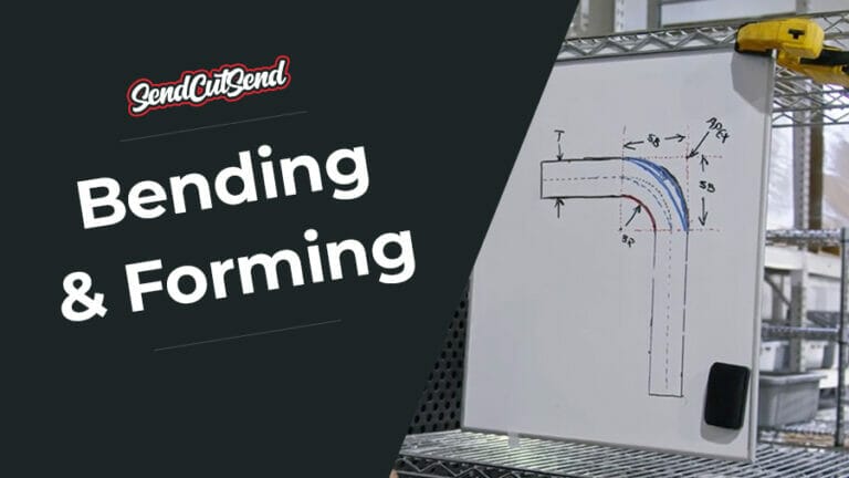
CNC bending opens up laser cut sheet metal to a new world of possibilities, turning your 2D parts into 3D. To help make sure you get your bends the correct sizes and in the right places we’ve created a Bending Calculator tool that calculates the complicated bend allowance and bend deduction values for you. To understand exactly what the tool does, this article will serve as a guide on how to calculate bend allowance and bend deduction. If you’d rather watch Jake walk you through the calculations in a video, you can scroll down a little further in this article for a link. You can also check our YouTube channel for a full playlist of videos that deep dive into bending.
Bend Allowance and Bend Deduction
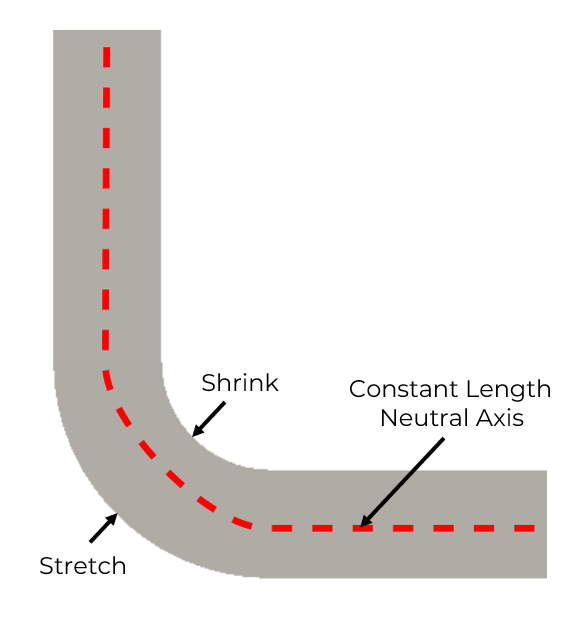
Let’s start with some basic descriptions before we get into the calculations. When a flat piece of material is bent, it gets deformed. The inside face of the bend compresses slightly and the outside face of the bend stretches. There is a theoretical line between the inside face and the outside face that stays the same length before and after the bend. This line is called the neutral axis. When the material is flat, the neutral axis is right in the middle between the outside and inside faces. But when the material is bent, the neutral axis in the bend shifts a little. The term K-factor is used to show how much the neutral axis moves off center in a bend. The neutral axis is important because it allows us to calculate the size of the flat pattern to start with in order to end up with a bend part in the size we want. You can learn more specifically about K-Factor in this blog article.
What is Bend Allowance?
Bend Allowance is the arc length of the neutral axis through the bend. It tells us how much extra length is generated by the bend deforming. If you know the size of your flat material and want to calculate how long the flanges will be after bending, Bend Allowance is what you want.
What is Bend Deduction?
Bend Deduction is how much shorter to make the flat length in order to end up with the right length after bending. If you know what size flanges you want to end up with after bending and need to calculate the size of the flat pattern to start with (and where to start your bend), Bend Deduction is what you want.
If you’re still not quite clear, keep reading and we’ll walk through a real example with numbers.
Bend Allowance Formula and Calculation Example
Bend Deduction Formula and Calculation Example
Let’s start with the formulas for bend allowance and bend deduction.
Bend Allowance = Angle(Π/180)(BendRadius+KFactor(Thickness))
Bend Deduction = 2(BendRadius+Thickness)·tan(Angle/2)-Bend Allowance
Angle is the bend angle you’ve decided to bend your flange. In this example it’s in degrees. Note when taking the tangent of the angle/2 that it’s the tangent of an angle in degrees. Some calculators expect your angle to be in radians. As we’ve done in the bend allowance formula, you can convert from degrees to radians by multiplying by pi/180. Alternatively, you can convert from radians to degrees by multiplying by 180/pi.
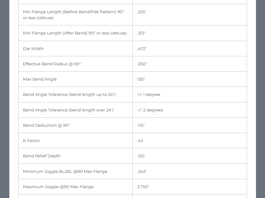
BendRadius is the inside radius of the bend. It is a property of the material and the equipment. We’ve provided this value for each material and thickness.
KFactor is a number to describe how far from the center the theoretical neutral axis moves when it’s bent. Again, we’ve provided this value for each material and thickness so you only need to look it up.
Thickness is simply the thickness of the material you’ve selected.
Other than the bend angle, you can find all of these properties on the materials page.
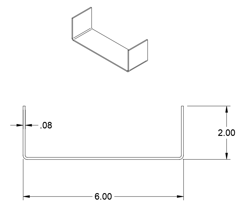
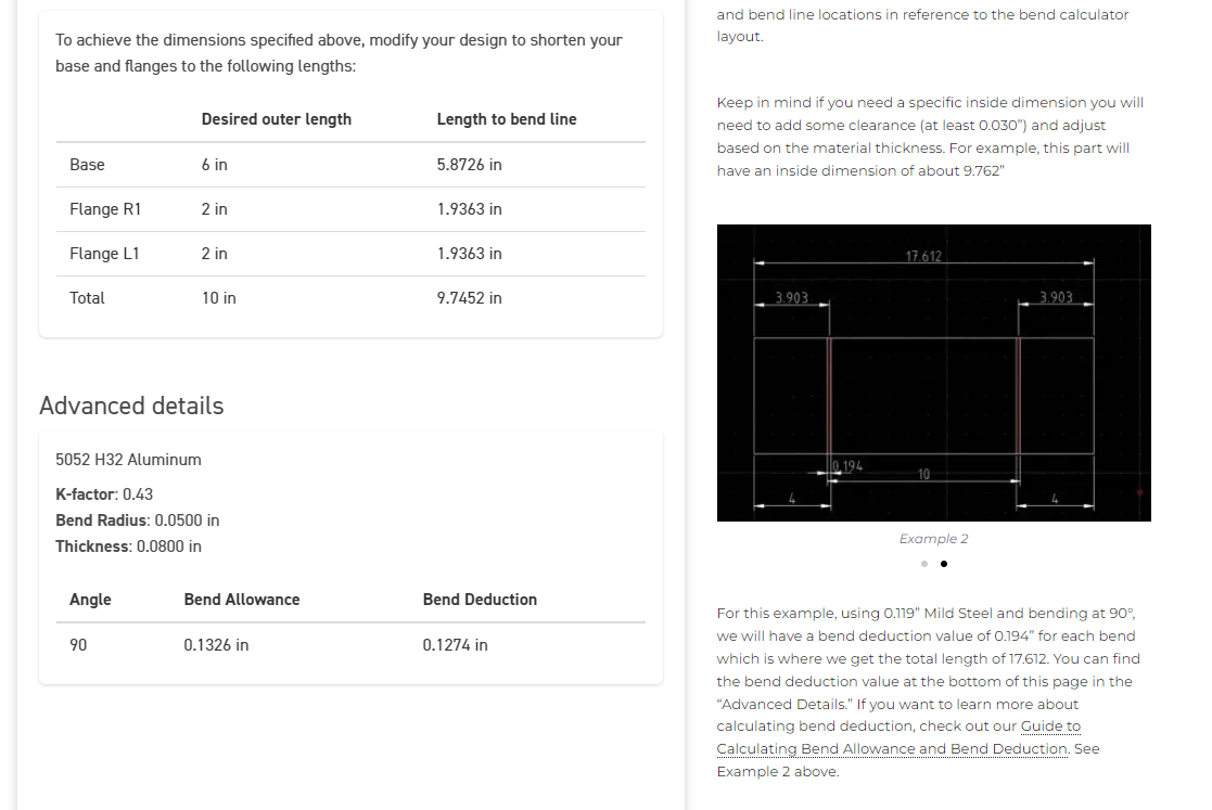
We can use a simple example part to illustrate exactly how this works. We want our final part to have a 6” long base, with a 90 degree, 2” long flange at each end. The part will be made from 5052 aluminum, .080” thick. To get our part made, we need to provide the flat with the appropriate dimensions. If we try to use 2”, 6” and 2” on the flat, we’ll end up with a part that’s a little too long due to the stretch during bending. To get the correct dimensions, we need to calculate the bend deduction for each bend.
For our material, we look up the necessary values on the 5052 aluminum material page for .080” thickness.
Angle = 90 degrees
Bend Radius = .050”
K-Factor = .43
Thickness = .080”

When we plug in the values for our example, we get a bend allowance value of .1326”. This tells us the neutral axis through the bend has an arc length of .1326”.
Now that we know how long that bend is going to be after it has been “stretched,” we can calculate the bend deduction. The bend deduction tells us how much of the length we need to remove (deduct) from the part in order to put the bend lines in the right place.
If we plug in those values from our example, we’ll get a bend deduction of .1274” for each bend (since the bends are identical in this example). If our bends were different angles, we’d get a different bend deduction for each bend.
We now know the number, how do we apply our bend deduction to the part in order to get the bend lines in the right spot?
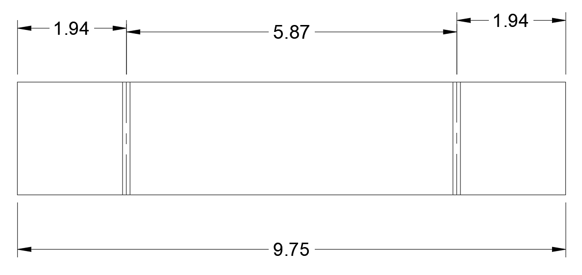
The bend deduction describes how much length we should remove to get the appropriate flat dimensions. For each bend, we subtract the value of the bend deduction. Each of our 2” flanges include half a bend, so we subtract half a bend deduction (.0637”). The 6” long base includes two half bends, so we subtract two half bend deductions (.1274”). This tells us how long each section needs to be and where the bend lines should be. By using these as our flat dimensions we should end up with a bent part in the final dimensions we want. Our 6” base becomes 5.8726” and our 2” long flanges become 1.9363” in the flat pattern. Instead of an overall length of 10” (6” + 2” + 2”) the flat pattern we start with should be 9.7452” long.
Provide a flat pattern with these dimensions to SendCutSend and the part you’ll receive will be 6” with 2” tall flanges.
How to Calculate Bend Allowance and Bend Deduction: A Video Guide
Note: it will be easier to understand the contents of this video and article if you’ve watched our previous video on the K-Factor in bending.
If you follow along in the video, we use the formulas for bend allowance and bend deduction. Then we subtract half a bend deduction from each side of the bend. Each 2” flange has half of one bend, so we subtract half the bend deduction we calculated from each of those flanges. The 6” base has two bends, so we subtract half a bend deduction for each (or a whole bend deduction). This tells us how much to shorten the total length of the flat part. When we actually bend the part, the “stretching” of the material will add the bend deduction dimension back into the total length of the part, enabling us to get the correct flange and base measurements.
Calculating all these values manually isn’t the only way to find the right dimensions for your material. If you’re using a CAD software with sheet metal tools, you can usually input the K-Factor and the bend radius values directly into the software and it will give you the same reduced values. It just depends on what software you’re using. Software packages like SolidWorks and Fusion 360 both have sheet metal bend tools built in.
If you’re not using CAD software, we’ve got you covered. We’ve created a tool you can use to calculate all these values for you.
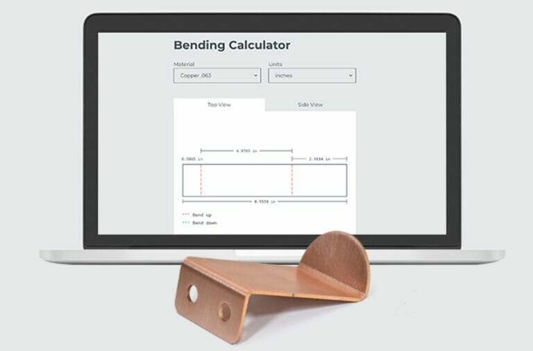
Introduction to the Bending Calculator
In our bending calculator, you can select your desired material, as well as the units of measurement your design uses (inches or millimeters). You can also add flanges, their dimensions and which side they’re on. To stick with our example from before, we’ve input two flanges and made our base length 6”. We’ve made a right side flange 2” with a 90° angle up, and a left side flange 2” with a 90° angle up.

As you scroll down the page, you’ll see that there is a top and a side view for your part. In the side view, you can see that our example part is a C-channel Bend. This is a great place to double check that your part looks the way you expect. It’s easy to accidentally bend at the wrong angle or in the wrong direction.


If you scroll down a bit further, you’ll see the Desired Lengths and the Modified Lengths. The desired lengths are what you want to end up with after bending. The modified lengths are what you’ll provide as a flat pattern to be laser cut prior to bending.
Finally, the “Advanced Details” that you can see are the material type, the K-Factor, the bend radius, and the thickness. These are the values the Bending Calculator uses to calculate the bend allowance and bend deduction. You could also find all these values in the materials page for your specific materials.
Conclusion
Our precision laser cutting and CNC bending processes make it simple to get highly accurate cuts and bends within +/-.005″ and 1°, respectively. We still want you to know what we’re doing in our shop to machine your parts to spec, so we’re continually adding to our list of resource articles like this one. If you have any other questions about bending, processing, or machining, these articles and our guidelines are the best places to start.
Or if you’re ready now to have bent sheet metal parts cut, processed, and shipped to you within a few days, upload your file to our app and get an instant quote today!