Laser cut sheet metal is incredibly versatile; here at SendCutSend we can bend, tap, finish, and even insert hardware for you, thanks to our ever-growing list of Services. But what if you need a complex round, oval, or conical part, but don’t know what the laser cut flat pattern should look like?
One of the best ways to leverage the power of a 3D CAD software like Solidworks for laser cut parts is to utilize a feature known as “flatten.” This trick works for bends, jogs, and rolled parts and allows you to design the geometry you need, then “unroll” the part.
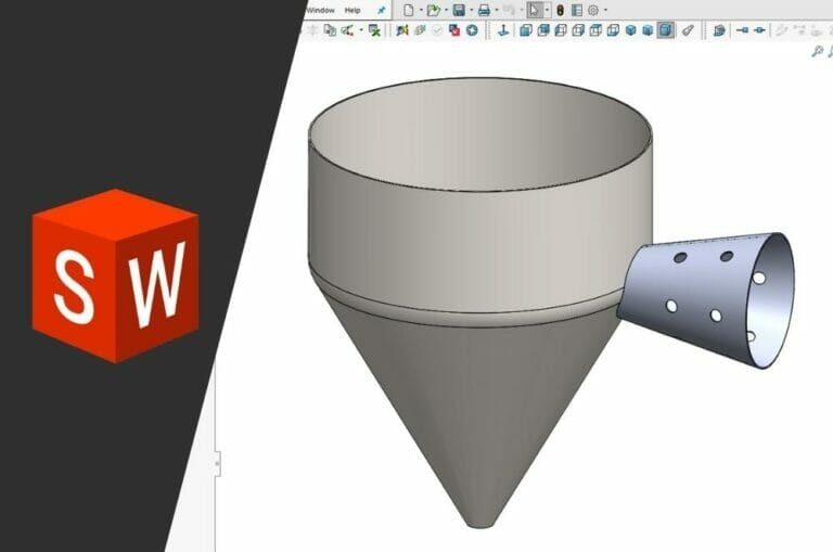
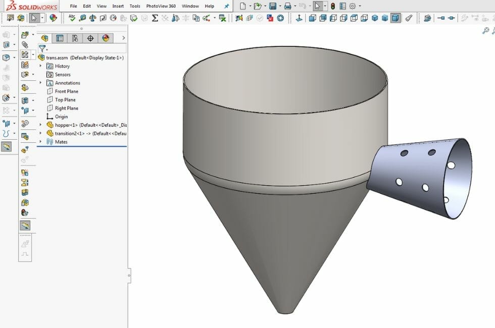
For instance, let’s say you need to weld this cone transition onto a standard hopper:
There are several ways to make this part: buy a cone with the correct taper, then modify as-needed to weld up to the hopper, and lay out and drill the holes by hand.
Or remove all the guesswork, reduce the fabrication time, and instead roll up a laser cut flat pattern yourself.
In this article, we’ll touch on sheet metal basics, how and when to roll a part, and run through a helpful Solidworks tutorial to answer some of those tricky questions.
Sheet Metal Rolling
By far, the most common way to purchase metals for end use is as “sheet metal”, which is defined as a flat metal less than ¼” thick (about 3 gauge) and going all the way down to as thin as 0.0125” (or 30 gauge). Sheet metal can be bent, rolled, formed, stamped, slit, spun and generally fashioned into just nearly any useful shape.
Advanced steel and aluminum sheeting is used heavily in automotive and aerospace industries, while in the commercial building sector, roofing, siding, roll flashing and décor are often made from mild steel, copper or brass sheet due to their formability.
This versatility comes in part because of the processes used in sheet metal manufacture: after being cast into a solid ingot, it is heated and run through a series of rollers, giving the steel plate a fairly uniform thickness and surface finish. This product is referred to as hot rolled steel sheet, and is most often pickled in an acid bath to remove the oxide layer. The next most common form of steel sheet metal is cold rolled steel, which is passed through another set of rollers, which allows the thickness of the metal to be held to a tighter tolerance and gives a stronger end product. We break down cold vs hot rolled steel in this article. Finally there is the annealing step, which removes internal stresses, improving weldability and allowing the sheet steel to hold its final shape evenly and without stress fractures.
The process is the same for corrosion resistant materials such as stainless steel, or aluminum sheet, but at the end of the day, what you purchase from the mill is still a flat sheet. If you need a tank, cylinder, cone, or just about any other curve, you’ll need to take that flat plate and put it through a slip roll.
Advantages and Disadvantages of Sheet Metal Rolling
Rolled and welded tube and pipe are by far the most common application for rolled sheet metal, but there are other advantages:
- Cost: Roll forming is often more cost-effective than stamping or extrusion, especially for long production runs. It minimizes material waste and requires fewer tooling changes.
- Production Speed: Continuous rolling can produce a significant number of parts in a short amount of time.
- Consistency: Roll forming offers excellent dimensional stability and repeatability, resulting in consistent and high-quality parts.
- Durability: The process can improve the mechanical properties of the material by work-hardening it, making the final product strong and durable.
- Reduced Post-Processing: Roll forming can often produce parts with finished features, reducing the need for secondary operations like welding, cutting, or machining.
There are also several disadvantages to rolling sheet metal:
- Initial Tooling Cost: Slip rolls and tooling can cost tens of thousands of dollars
- Limited Material Options: Not all metals can be effectively roll-formed.
- Material Thickness: Extremely thick or thin materials can be challenging to roll-form. Thin materials may buckle, while very thick materials may require excessive force and energy.
- Changeovers: Changing from one profile to another or adjusting for different dimensions can be time-consuming and may result in production downtime.
Although SendCutSend does not offer sheet metal slip rolling at this time, using the information in the guide below, and our laser cut flat parts, you can become a metal rolling power user in no time.
How to Prepare Rolled Sheet Metal Parts in SolidWorks
Let’s walk through the steps necessary to flatten a rolled sheet metal part in Solidworks to prepare it for laser cutting.
Step 1: Use “Cut-Extrude” to make a parting line in your rolled part
First, open your transition part file and make a parting line which will be the seam when rolled up.
You can use the Cut-Extrude feature:
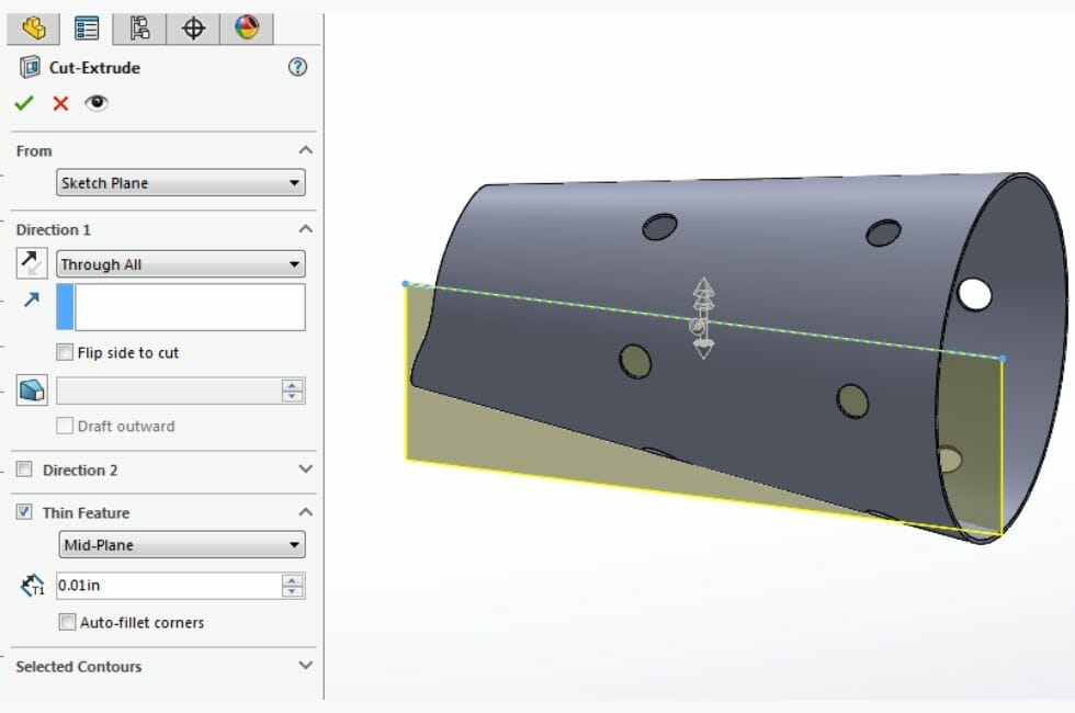
For this example, a sketched line is being extruded through the part as a thin feature with a cut thickness of 0.01”. This ensures when the final part is rolled up, it won’t have a big gap at the seam.
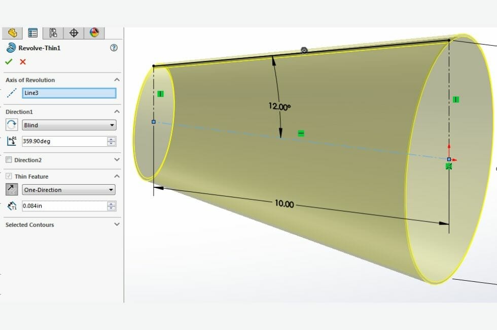
Or, if it’s a revolved part, simply reduce the revolved degrees so it leaves a small gap:
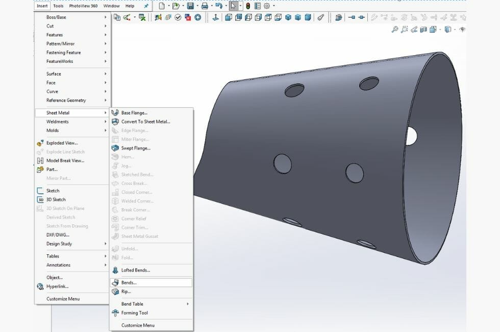
Step 2: Insert your bends
Next, you’ll want to select the “Insert Bends” feature from the sheet metal toolbar.
Step 3: Highlight the seam
Under the “Bends” menu, select the inside edge from the seam to highlight it as shown in the image below.

Step 4: ”Unsuppress” the auto-generated flat pattern
The final step is to take the auto-generated flat pattern and unsuppress it. This brings the flat pattern into view on the model, resuming the feature and allowing you to export correctly.
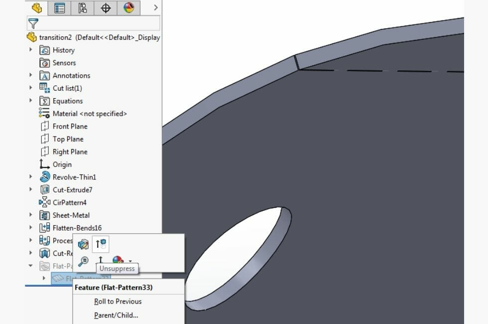
The result is a flat pattern with a bounding box which you can save as a .dxf using the instructions here.

You’re ready to upload to SendCutSend’s instant quote tool!
Using this method means the rolled part features can include holes, edge profiles, or other complex shapes, allowing much faster fabrication, tight fitment without any modification, and no difficult hole drilling on concave surfaces. There are lots of other handy tricks that you can use to simplify your build process and optimize your laser cut parts, so be sure to check out our other tips and tutorials.
When you are ready, upload your file to our instant quote tool, select your preferred material and quantity, and we’ll ship your parts within 2-4 business days!
Try our SolidWorks Plugin
If you are using SolidWorks 2021 or newer, check out our SolidWorks Plugin. You can upload to SendCutSend and get live quotes without ever leaving SolidWorks.