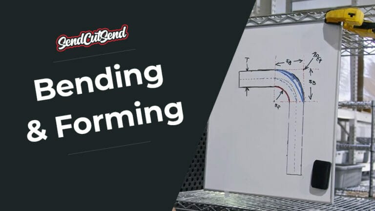
Designing bent sheet metal parts can be one of the more difficult processes in manufacturing. It may feel daunting learning how to set up your file for sheet metal bending, but through our years of machining and fabrication, we’ve learned a few tricks for making sure your file is set up correctly. These will help you get the best possible outcome from our sheet metal bending service.
From laying out your part in 2D to choosing the correct bend line indicator, we’re covering everything you’ll need to know about setting up your file for sheet metal bending. As always, be sure to read our bending guidelines as well before uploading your part!
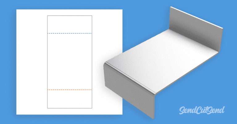
All bent parts should be in a 2D, flat file
When you send us your bent sheet metal design, we first have to laser or waterjet cut it. This means your file has to show your part laid out flat instead of in the original 3D format. Most supported CAD programs have sheet metal rules, which is what you should be using to design your part. If you are using a vector graphic or 2D design software, there is no need to change your export because your bent part will already be laid out flat.
Our preferred CAD program is Fusion 360, which is completely free for hobbyists. If you are designing your bent part using Fusion 360’s sheet metal feature, laying your part out flat and exporting it as a .dxf is fairly simple.
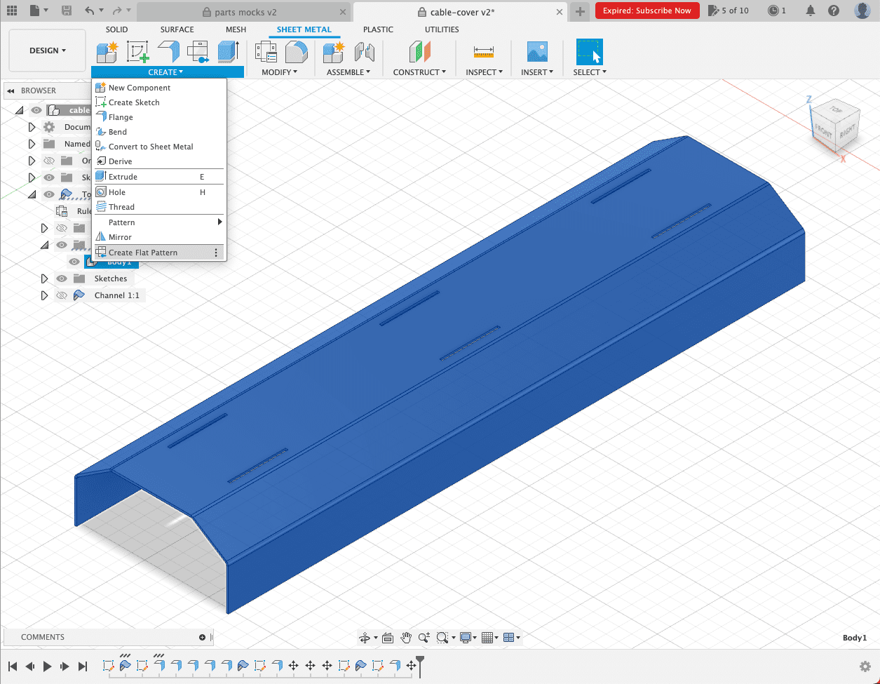
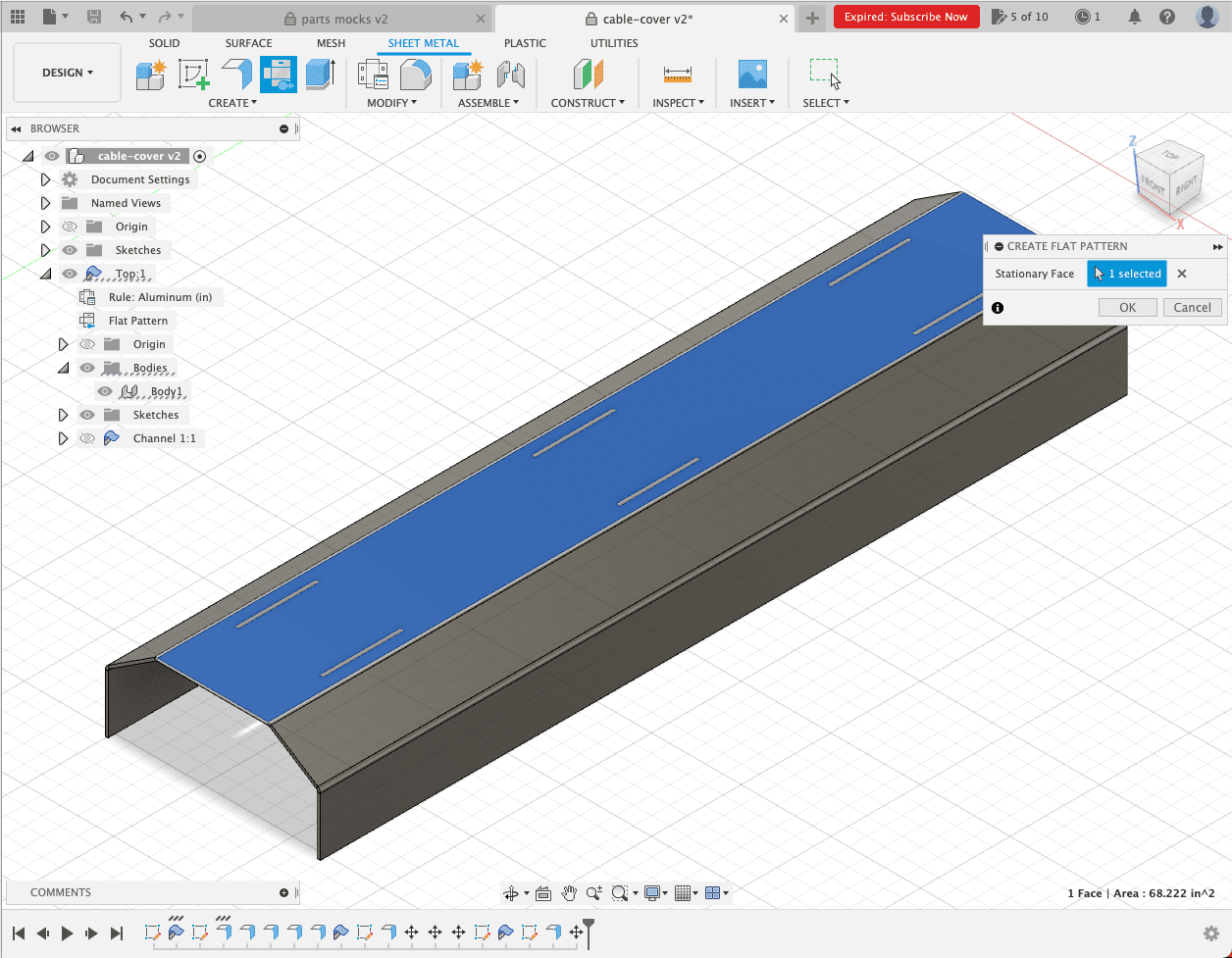
With your 3D part modeled in Fusion 360, click “Create Flat Pattern” underneath the “Surface” option. With that open, you need to select the stationary face of the part that all your flanges are bent from. When you are finished with that and select “OK,” you’ll see your part laid flat with all bend lines already included. This is what you will export as a .dxf and upload to our website.
Do not leave notes anywhere in your file to indicate the direction of the bends or their angles. You will be able to indicate bend angles and directions when you upload your file for quoting, so there’s no need to leave additional notes.
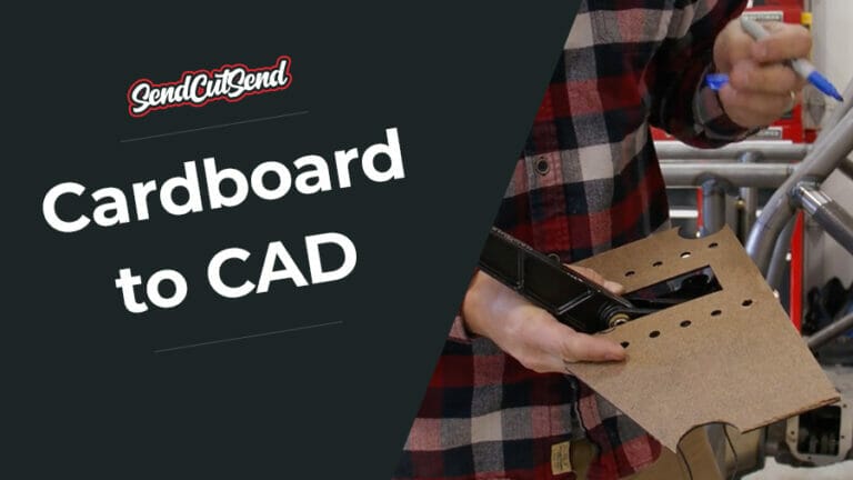
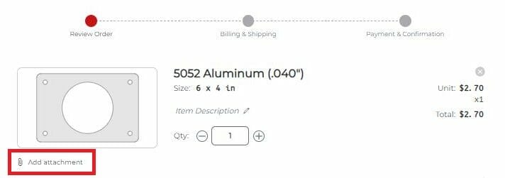
In the absence of notes on your file, we encourage you to attach a 3D model image or callout sheet to the line item during your checkout process so we can see exactly how your bent sheet metal part is meant to function. This is also helpful for us to reference during production!
Choosing the right bend line indicator
You will need to put bend lines in the file to indicate where we should bend your parts. There are a few different ways to indicate bend lines, and each software you use requires something different.
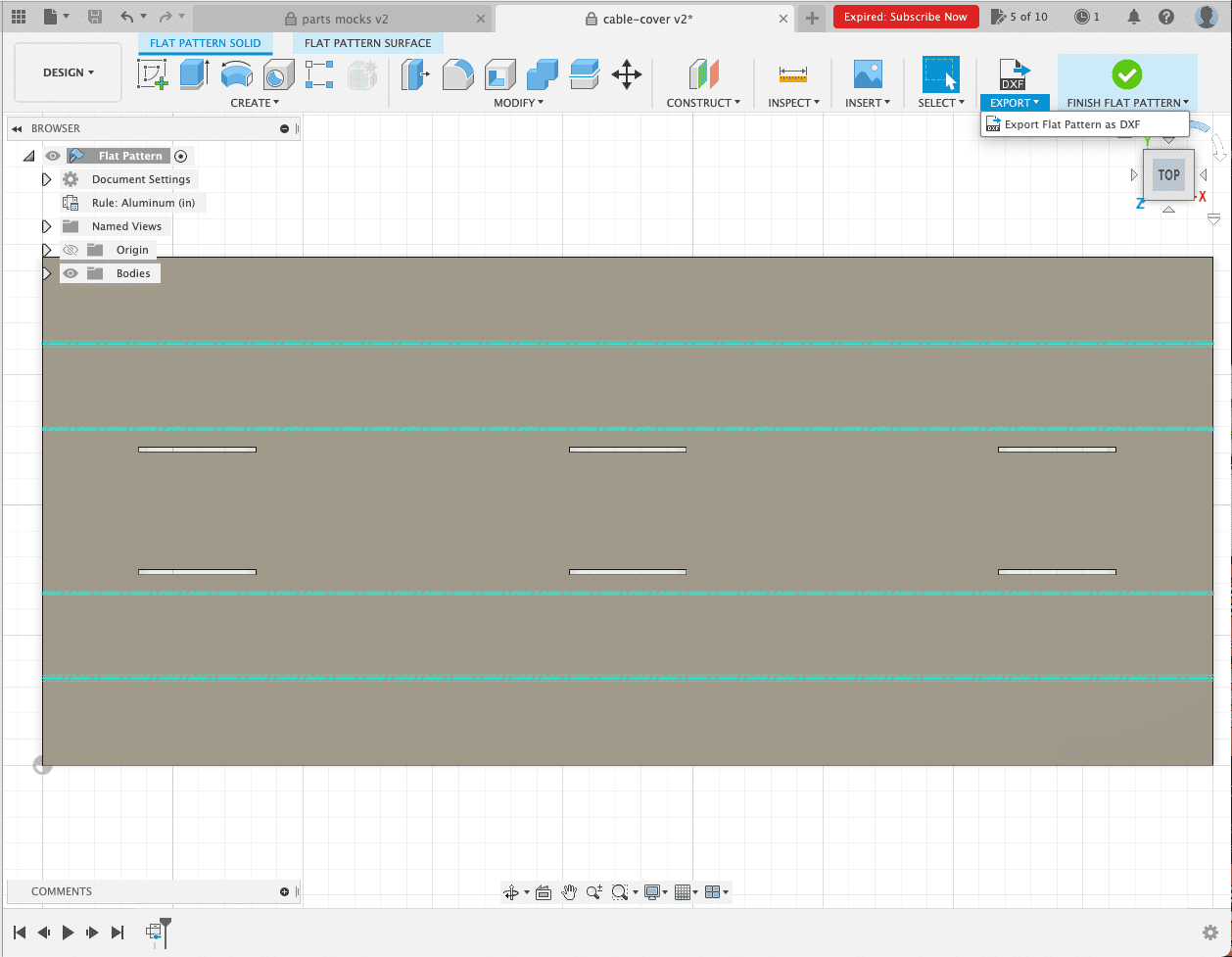
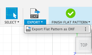
If you followed our above instructions for Fusion360, the bend lines will appear automatically with the “Create Flat Pattern” function. They will default to a solid line, which is our preference for bent sheet metal parts designed in Fusion360. To achieve correct bend lines in Fusion 360, you will need to define the dimensional thickness of your part , convert it to sheet metal, create a flat pattern (as shown above), export as a .dxf, and in the “Export as a .dxf” dialogue, select “Convert splines to polylines.” This will result in 3 solid lines to export. The center line will automatically be detected in the SendCutSend app for bending.
All other programs have different methods for indicating bend lines, so refer to this chart to see what style we prefer based on which software you use. If you’ll be exporting a 3D .step or .stp format file, please see our 3D File Guidelines.
| SOFTWARE | FORMAT | BEND LINE |
| Fusion360 | .dxf, .step, .stp | Solid line (default) |
| Adobe Illustrator | .ai | Solid, separate color from cut lines |
| SolidWorks | .dxf, .step, .stp | Dashed line (default) |
| AutoCAD | .dxf, .step, .stp | Dashed line |
| CorelDraw | .eps | Solid, separate color from cut lines |
| Inkscape | .eps | Solid, separate color from cut lines |
Final sheet metal bending considerations
As you’re setting up your file for sheet metal bending, there are a few final design things you should keep in mind:
- Keep all features and holes a minimum distance of 0.255”-1.150” from the die lines. The minimum distance changes based on what material and thickness your bent part is using, so check in with our support team to make sure any design features and holes are far enough away from the die line. This will prevent warping on your part. See our Bending Deformation Guidelines for more information.
- We do not offer cosmetic protection for your parts during bending, so you may see die marks from the bending process. You can remove these fairly easily with a random orbital sander.
These are just a few design considerations you need to be aware of as you’re setting up your file, so make sure to read our full sheet metal bending design guidelines before uploading your file to our website. And if you have any questions at all, our support team is always here to help you find the answer.