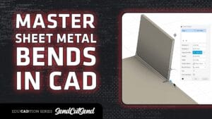
In chapter 5 lesson 7, Jake explains bend relief, why it’s necessary, where it goes, and how to design it properly to prevent cracking, tearing, and deformation during bending. While earlier lessons focused on bend calculations and deformation, this one dives into the practical design fixes that make your parts stronger and easier to manufacture.
Jake covers two key scenarios: standard bend reliefs (used when a flange doesn’t span the entire bend length) and corner reliefs (used when two bends meet). He explains how bending creates tension and stress risers that can lead to cracks over time, and how adding small relief slots or holes eliminates those problem areas.
He also shares rule-of-thumb dimensions for reliefs, making their width about 50% of material thickness, and their depth equal to the bend radius plus material thickness plus .020 inches—along with guidance for designing circular or square corner reliefs based on your material and application. Finally, Jake notes that most CAD programs like Fusion and SolidWorks can automatically add bend reliefs, but understanding the “why” behind them helps you make better design decisions.
What You’ll Learn:
What bend reliefs are and why they’re critical for manufacturable designs
How to prevent cracking, tearing, and stress risers in bent parts
The difference between standard and corner bend reliefs
Rule-of-thumb dimensions for relief width and depth
When to use round vs. square corner reliefs
How CAD software can automatically add bend reliefs
Why proper bend relief design ensures cleaner bends and longer-lasting parts