Utilizing bend reliefs in your design can open up new geometry options and tighter tolerances for your bent parts. With years of experience designing, machining, and bending parts with bend reliefs ourselves, we’ve put together this comprehensive guide to designing bend reliefs to help make your parts even more successful.
What are bend reliefs for sheet metal parts?
Bend relief is one of those small details in a bent part that’s easily overlooked. In parts where it’s required, leaving it out can at best cause unwanted tearing, or at worst make your part nearly impossible to physically make (at least the way it’s drawn). So what is bend relief?
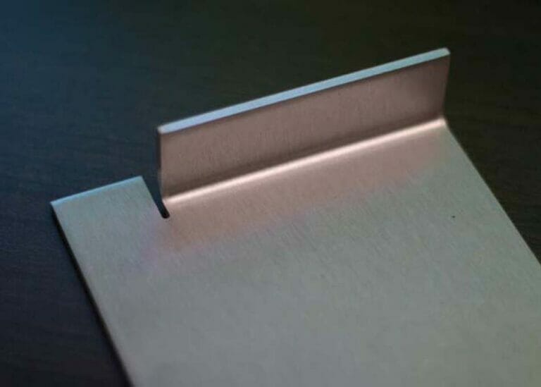
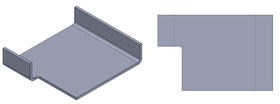
Bend relief is simply the removal of a small area of material at the edge of a bend where the curved part of the bend meets the flat surrounding material. You are making a controlled cut to both sever the bending material from the adjacent flat material, and making space for the bent material to deform into.
Bend Relief vs Corner Relief
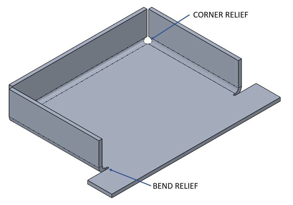
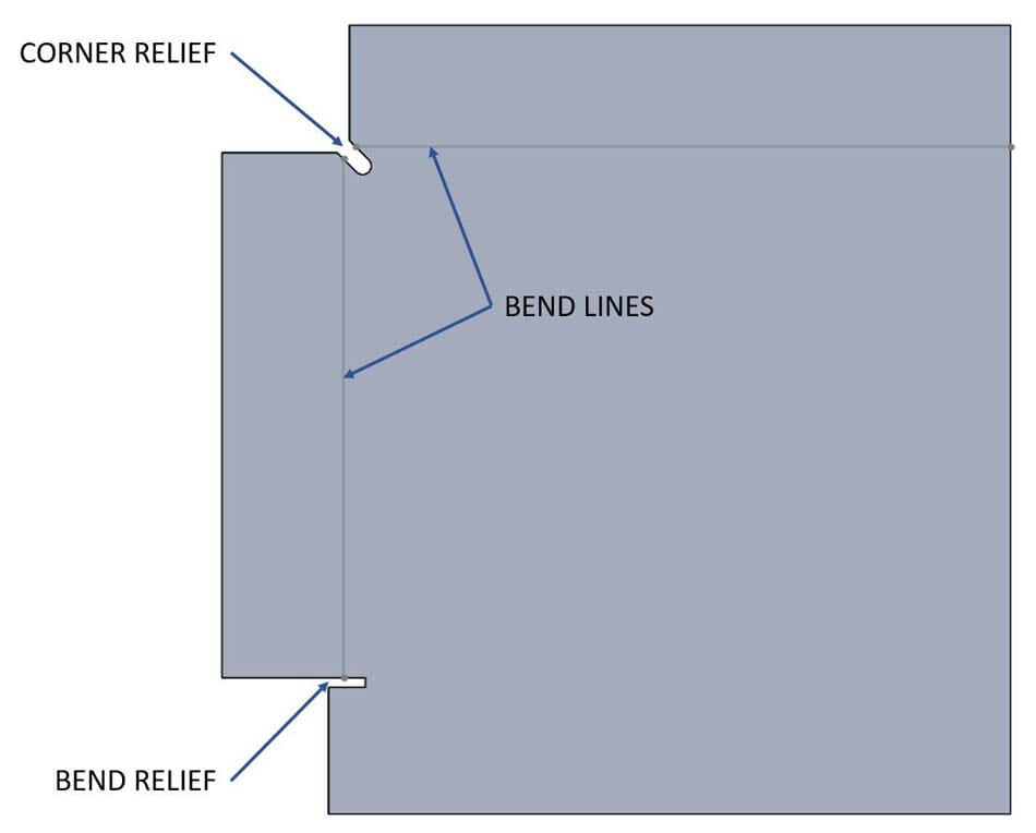
You may hear some different terms used to describe bend relief. Typically when there is a single bend with flat material at one or both ends, the relief is called “bend relief.” When there are two (or sometimes three) bends that meet in a corner, like a tray or box, the relief is often called “corner relief.” In both cases, the idea is the same: to remove enough material from the edge of the bend that the bend can be formed.
When and why do bent corners need bend relief?
Some bends require relief and ignoring it can have negative consequences for your part. When material is bent, some of that material is stretched (the outside of the bend) and some of the material is compressed (the inside of the bend). The material that gets compressed doesn’t just get smaller, it actually has to go somewhere. That “somewhere” is typically out to the sides of the bend.
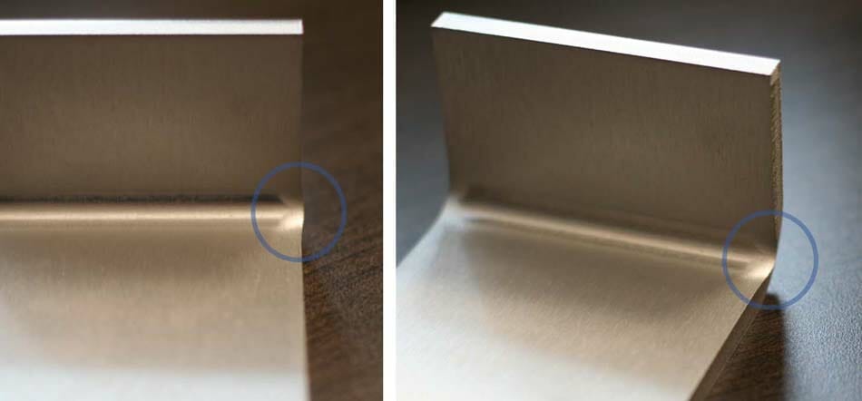
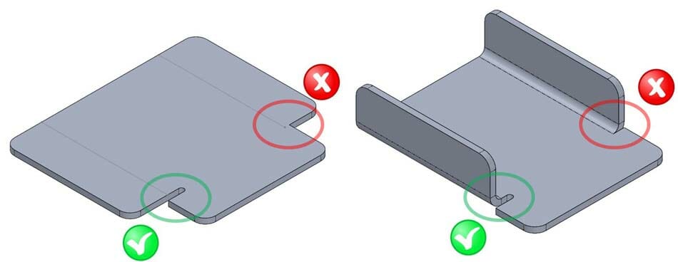
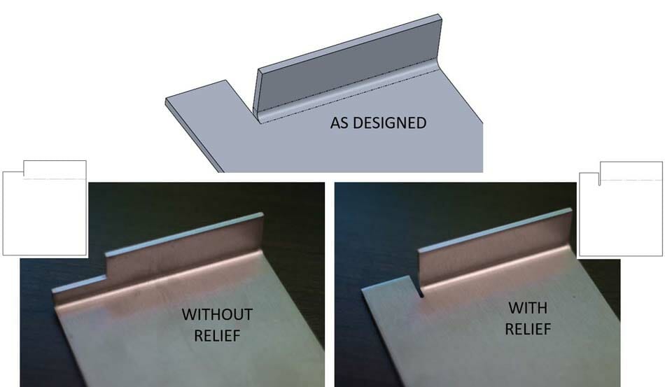
In some parts, that little bit of extra material squished out doesn’t cause any problems. But if your part has a bend located beside a flat (or even another bend), there’s no room for that squish. A press brake can be pretty convincing, so that squish is going to go somewhere. If you haven’t provided a place for it to go, it’ll find its own space. That can cause unwanted warping or tearing in the part and you’re left with a shape other than the original design. Similarly, if you need your bend to stop in the middle of the part rather than extend all the way across the width, the bend relief separates that material and allows the bend to happen on one side, while the other side stays flat.
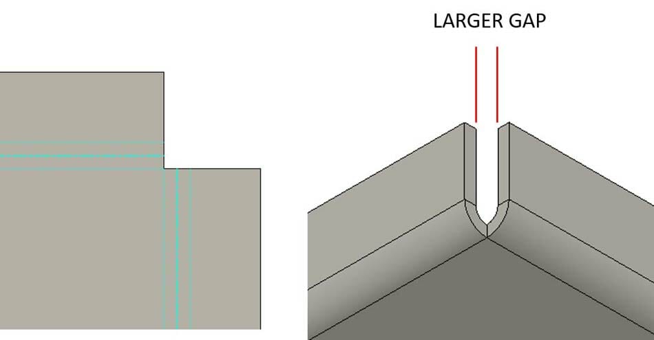
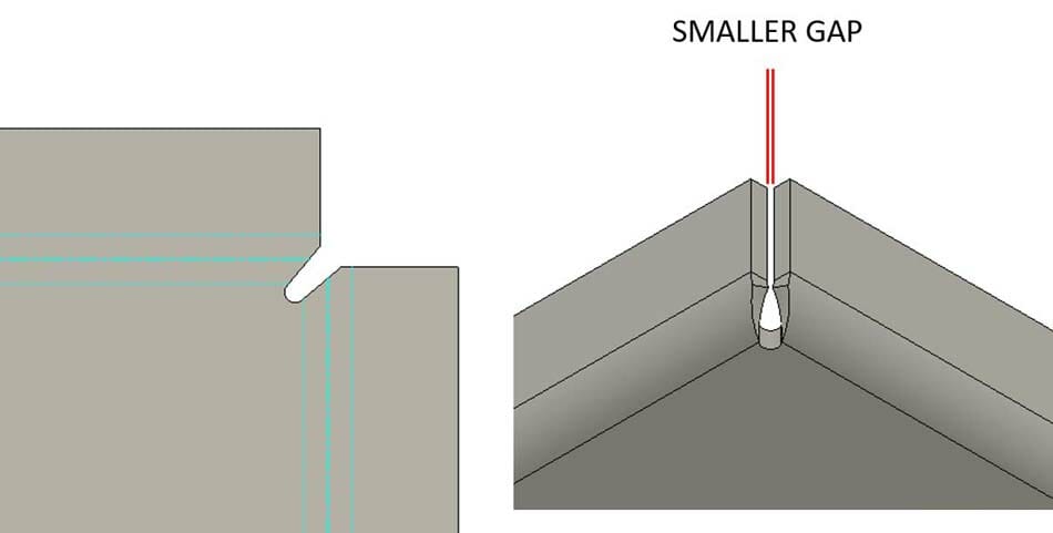
Let’s look at an example where two bends come together at a corner. If the corner needs to be closed up for aesthetics or maybe to be welded, you’ll want the gap to be relatively small. A small relief in the corner allows the edges of the bends to come together tightly.
Not all bends require relief. For example a bend along the full width of a part. There’s no flat material out at the edges of the bend. You’ll just want to be aware that after a bend, the edges along the side won’t be perfectly flat anymore, there will be a slight bulge near the inside. If flat edges are something your part needs, you’ll probably want to file or grind away that material after it’s bent.
How to figure out what size your bend relief should be
So we’ve discussed what bend relief is and why it’s needed, but how do you know how much material you need to remove? Basically you want to remove the material at the edge of the bend. We provide a simple calculation you can do to determine a safe minimum size for your bend relief.
Width: The width of your relief should be at least half the thickness of your material.
Relief Width = material thickness / 2
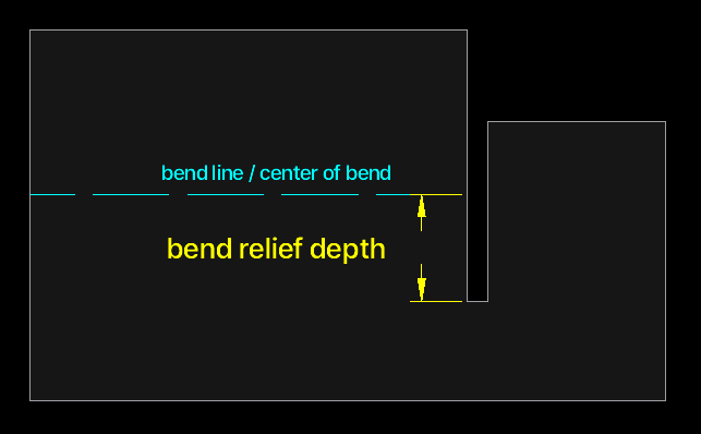
Depth: The depth of your relief should be at least the material thickness + the bend radius + .02” (0.5mm) measured from the bend line. That extra .02” provides just a little added clearance.
Relief Depth = material thickness + bend radius + .02″
Not big on math? No worries, we’ve got you covered. You can look up the relief depth we suggest (along with tons of useful info) for all the materials and thicknesses we offer on the materials page. Use that in your design and you shouldn’t have any problems with your relief.
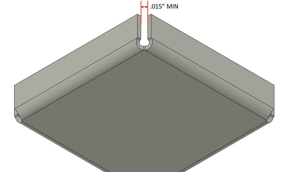
When dealing with bends that meet at a corner, we also recommend keeping the gap between the flanges to a minimum of .015” (0.4mm).
Note: Bend radius is dependent on the tooling used to do the bending along with the material properties. At SendCutSend we use air bending, so we provide the effective bend radius values for all the materials we offer that are bent using our specific tooling. Learn more about our bend radius specifications.
If you’re doing the bending yourself, you may want to do a test bend to find out what your effective bend radius is.
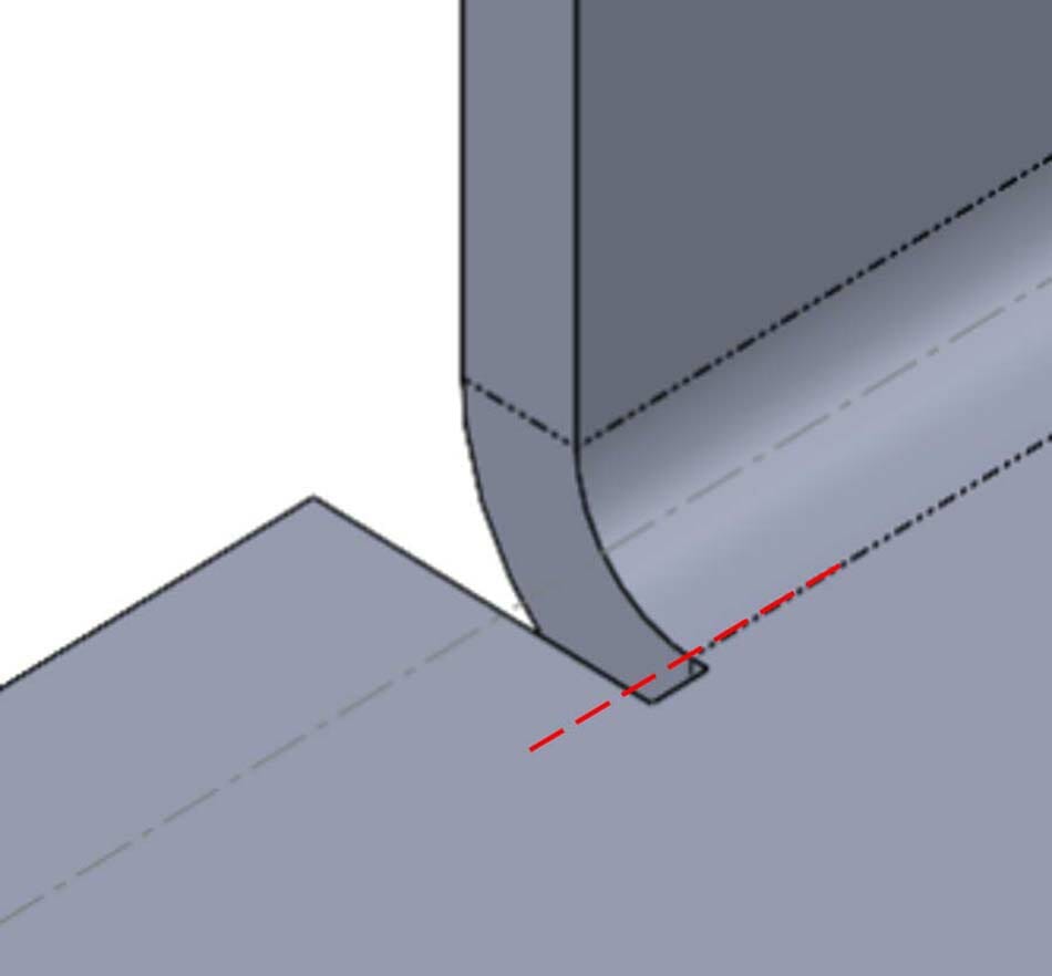
If the numbers don’t make sense or you have trouble figuring out where to measure from, just keep in mind that a properly sized relief extends at least as deep as the start of the bend.
5 common shapes for bend relief
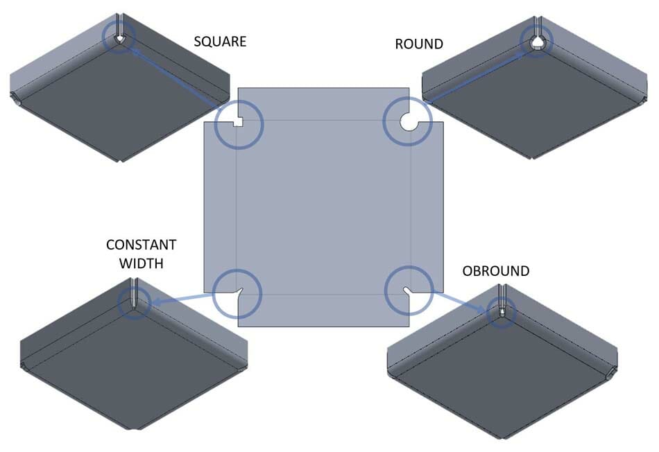
The final thing to determine about your bend relief before actually implementing it in your design is what shape it should be. The good news is if your part is being laser cut or waterjet cut, it doesn’t really matter. There are some advantages and disadvantages to different shapes, but one of the biggest factors in choosing the shape is aesthetics. Some common shapes are square or rectangular, obround, and round.
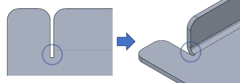
- Rectangular – Square inside corners are typically avoided in parts that have to carry loads because they can create areas of stress concentration and that’s where cracks like to start.
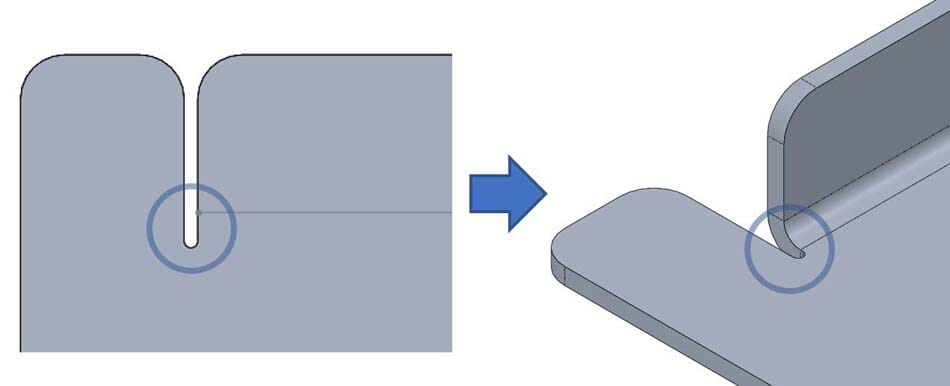
2. Obround – Obrounds are basically slots with rounded ends. Obrounds are common and can be a good choice if you’re trying to keep gaps to a minimum. For example a corner between two bends that you want to seal up after bending. An obround relief can minimize the gap and make welding or seam sealing easier.
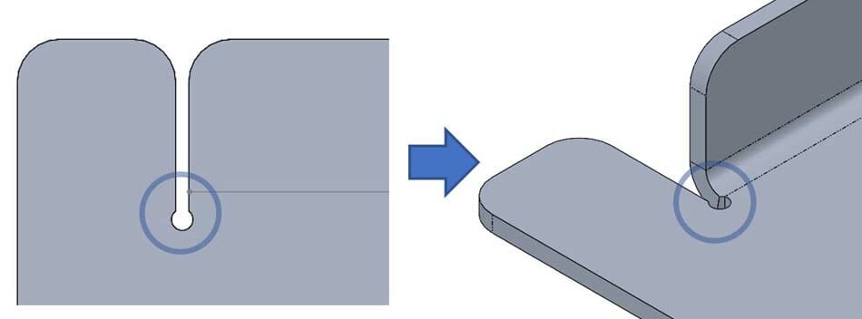
3. Round – Rounds are simply circular cutouts. These are common in handmade parts because they can be easily created with a drill. Round reliefs tend to leave slightly larger gaps than some of the other styles we’ve mentioned here.

4 .Custom Shape – A big benefit to laser cutting is that unique shapes can be cut just as easily as simple shapes. If your project needs an extra level of detail, you can use this to your advantage and get creative with the shape of your bend relief.
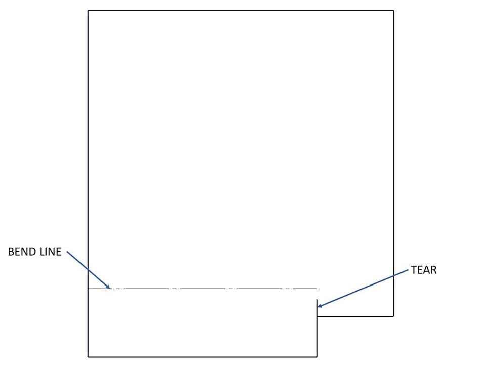
5. Tear – You may see tear as a shape option in some software packages. Choosing tear tells the software to create a zero width slice to separate the material where the relief should be. Since cutting tools with zero kerf haven’t been invented yet (even lasers have a small kerf), it’s best to avoid this shape if you want your parts to come out clean.
How to design bend reliefs for sheet metal with CAD software
There are two common ways to add bend relief to your design. One way is to do it manually. This is an option in any tool you use to create your design. The same way you draw the other features of the part, you draw out the bend relief at the ends of any bends that require it using the appropriate dimensions discussed above. Drawing your relief cut manually also has the advantage of giving you complete control over its shape. If you’re looking for a custom bend relief shape, this is your best option.
If you don’t need as much control over your bend relief, the other (arguably easier) option is to use the sheet metal features built into some common 3D CAD software packages. Not all software will offer these tools, but the freely available Fusion includes it, as do most purchasable CAD software packages like SolidWorks and Creo.
CAD with integrated sheet metal tools offer the ability to quickly add bends to your design, and when necessary, bend relief. It’s important to note that not all software measures relief in the same way. Relief width is fairly consistent across different software packages, but depth is not always measured from the same reference. Both Fusion and SolidWorks measure the bend relief depth from the start of the bend.
How to design bend reliefs in Fusion
Tip: we strongly recommend downloading and importing our premade Fusion gauge tables so you can easily use our bending specifications (bend radius, K factor, and relief depth) for the material thickness you’re designing with! Our Fusion gauge tables allow you to import the right bending specifications with just a few clicks.
At SendCutSend the bend radius and K factor are set for each material thickness and cannot be changed, so it’s essential to set up your parts using our specifications to ensure your parts turn out as expected within our established bending tolerances.
In Fusion there are two locations to control bend relief: you can control the default settings for your design and you can override the default settings for each individual bend if you need to.
The default settings can be found under the sheet metal tools, “Modify” menu.
Default settings can be controlled for the whole library of materials, or just for this particular design once you’ve created a part using one of the materials. You may need to convert your part to sheet metal before it shows up in the “In this design” section.
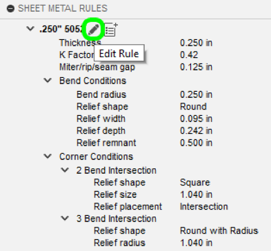
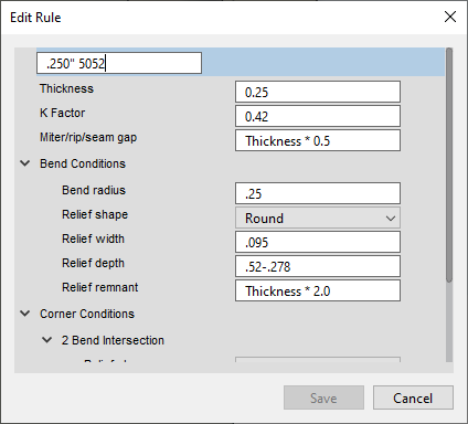
Here you can specify many of the sheet metal specific properties including bend radius, K-factor, and bend relief dimensions. These can be fixed values or formulas based on the material thickness. (Note: you can find all of this information for your chosen material and thickness in our bending calculator as well.)
The default settings will automatically apply to all bends. If you need to change the bend relief for any particular bend, you can find the override settings in the individual bend feature settings.
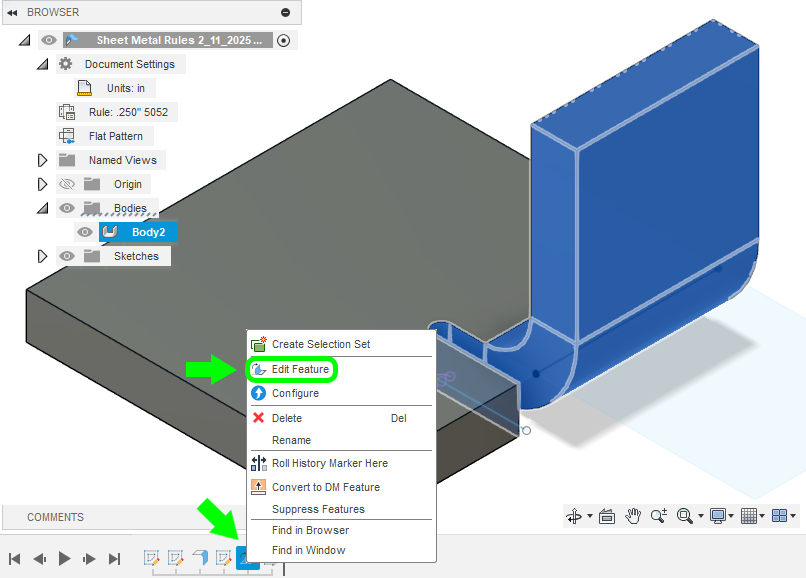
All the default settings can be overridden on each individual feature, including bend radius and bend relief options.
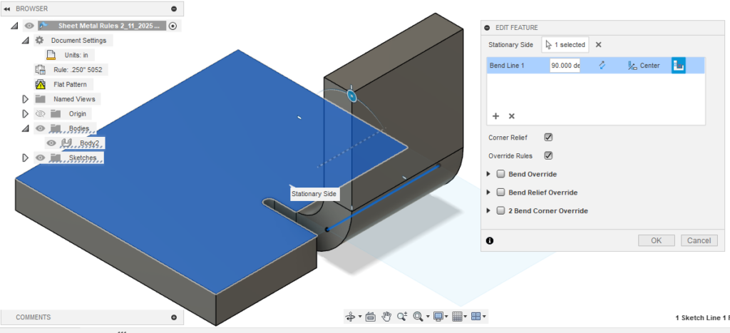
That being said, do not override bend radius options for individual flanges! We don’t offer customizable bend radii per material or per flange at this time, so your whole part should be set up with the bend radius specification we list for the material thickness in our Material Catalog.
How to design bend reliefs in SolidWorks
Tip: we strongly recommend downloading and importing our premade SolidWorks gauge tables so you can easily use our bending specifications (bend radius, K factor, and relief depth) for the material thickness you’re designing with! Our SolidWorks gauge tables allow you to import the right bending specifications with just a few clicks.
At SendCutSend the bend radius and K factor are set for each material thickness and cannot be changed, so it’s essential to set up your parts using our specifications to ensure your parts turn out as expected within our established bending tolerances.
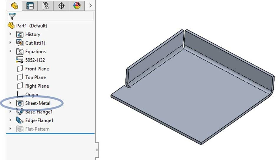
In SolidWorks you have a few different places you can include bend relief. The first is in the initial Sheet-Metal feature that is created when your part is made using the sheet metal tools (or converted to sheet metal). From here you can select to have relief added automatically on bends that require it. This works well for standard bends, but not for corner relief (we’ll get to that in a bit).
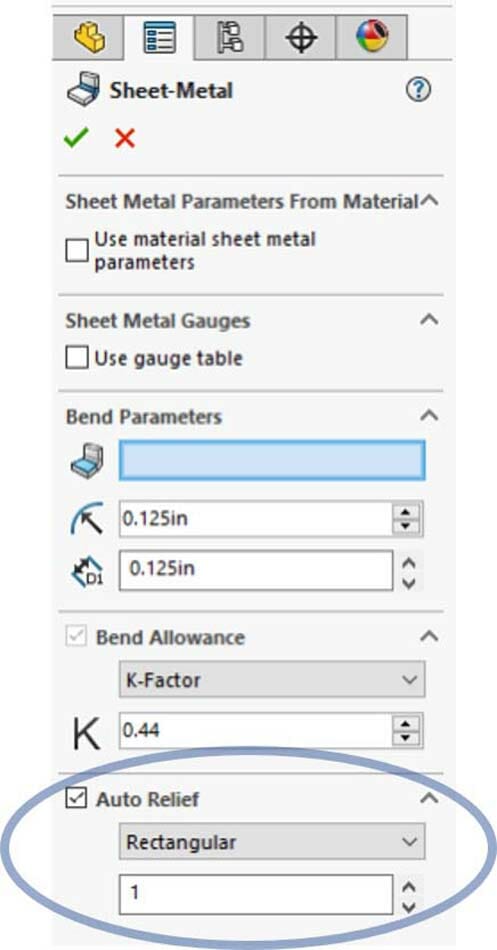
You can choose between shapes like rectangular, obround, and tear. Instead of entering a width and depth, you’re limited to just the ratio of each compared to the material thickness. In this example, a ratio of 1 and material thickness of .125 gives a relief width of .125 and relief depth of .125..
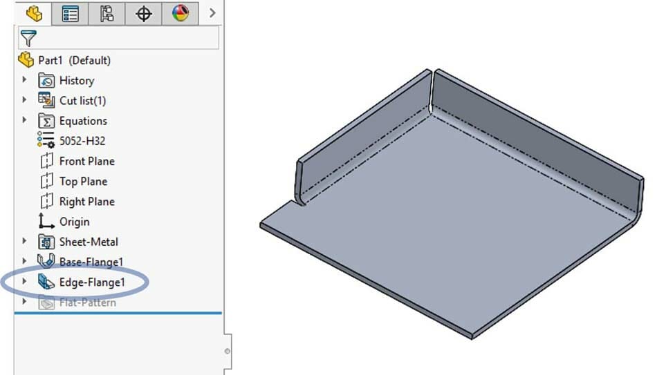
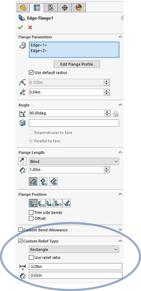
The second option for bend relief in SolidWorks is in the Edge-Flange feature itself. Here you have a little more control. Rectangular, obround, and tear are still the only shapes, but here you can choose whether to use a ratio to the thickness or specify relief width and depth independently.
The last method for creating relief in SolidWorks applies to corner relief. We discussed previously that corner relief is the relief where two bends meet in a corner. Corner relief can be added as a separate feature. Here you have a few more options for shapes and dimensions.
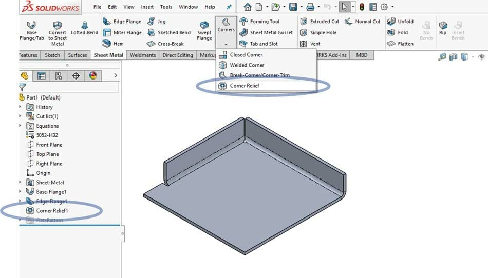
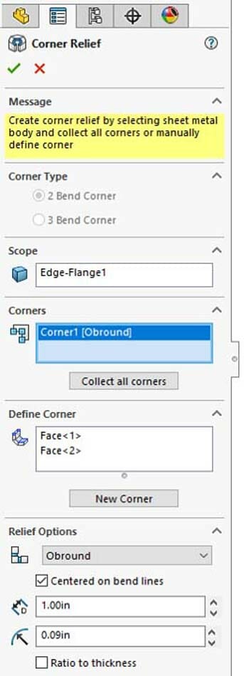
In the corner relief feature you can specify the corners the settings will apply, either a single, multiple or all corners. Multiple corner relief features can be created if you need different settings for different corners.
Examples of when sheet metal parts do and don’t need bend reliefs
Using a CAD tool to help you visualize your bend part can help, but if you’re still not sure whether your bend requires relief or not, below are some examples of bends that do and don’t require relief. Each bend has two edges, and some bends require two, one or no reliefs. Notice on the example part below that at both ends of every set of bend lines, material has been removed.
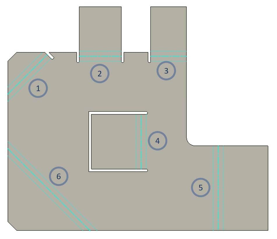
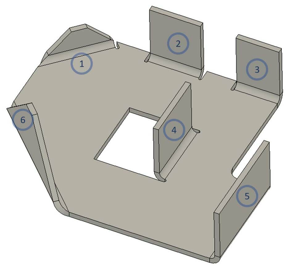
- Bend #1 and #6 are very similar, the difference is that in bend #1, the right side of the bend stops just short of the edge of the part. Because of stopping before the edge, a relief is required. If you didn’t need to stop the bend before it reached the edge, a relief on that side may not be required. On the left side, the bend extends all the way to the edge and there is no additional material in the way, so it’s possible to bend it without a relief in thinner materials.
- Bend #2 takes place in the middle of the edge with unbent material on both sides. This requires relief on both sides.
- Bend #3 sits on the edge of the plate, with no flat material to the right. No relief necessary on the right side. On the left, similar to bend #2, a relief is required to make room in the unbent material.
- Bend #4 is often referred to as a window bend. If you intend to create a bend like this in your part, you will need relief on both sides of the bend.
- Bend #5 is almost identical to bend #3, they both have one side along the edge of the plate and the other side in the middle. The important difference is that bend #5 is out away from the unbent material. Because of this bend #5 does not require any relief, especially because the bend is square to the material edge.
- Bend #6 runs from one edge of the plate to the other. Because there is no unbent material directly to either side of the bend, it’s possible to bend it without relief in thinner materials. However when the bend is oriented out of square with the edge of the part, the material may curl and deform. The thicker and stiffer the material, the greater the need for bend relief to prevent deformation and ensure the flange bends successfully.
More information on best practices for sheet metal bending
Depending on the shape of your part and location of your bend, you may need to include bend relief to avoid tearing or warping along the edges where your part transitions from flat to bend. Not all bends will require relief, but when they do you can look up or calculate the size you’ll need. Designing bend reliefs manually gives you more freedom but is more difficult to calculate, or if you’re using software with sheet metal tools built in, you can have it add the relief for you.
Want to know more about bending? We’ve put together plenty of bending resources in our blog to help you with your designs.
- Sheet Metal Bending and Forming Guidelines
- Guide to Configuring Bends Using our App
- Designing for Bending
- CAD tutorials
When your designs are ready, upload them to our website to get instant pricing!
