Sheet Metal and Plastic Bending Calculator

Use SendCutSend’s bending calculator to input your desired material and the units of measurement for your design to get the calculated bend allowance and bend deduction for your part before sending it to our lasers. The calculator also allows you to input flanges.
Play Video

Using the Bend Calculator

Step 1:

Select material type, thickness, and desired units

Step 2:

Enter your base length

This represents the overall outside desired dimension of the base, center, or largest section of the part. If this was a U-channel, this would be the outside dimension after bending of the center section.

Step 3:

Enter your flange dimensions

These are also entered at the desired outside dimension after bending. You can adjust the flanges to be on either side of the base by selecting the left or right position.

Formed flange lengths should always be measured from the apex of the bend.

This will result in the Sketch view (see below) showing the location the bend lines need to be placed in the flat pattern with the bend deduction taken into consideration.

Step 4:

Select your view

In the Results section, the default option is a flat view of the part you are gathering data for. You can select the 3D view to ensure your bends are as you expected.

Step 5:

Adjust your design

You can then adjust your design to match the overall outside dimension (17.765”) and add the bend lines (3.903”) from the edge of the part. Once this is bent, it will have the desired outside flanges (4” outside dimension) and base (10” outside dimension). See Example 1 below.

If you’re utilizing 3D CAD software, draw the part with the flanges in place using the sheet metal function in whatever CAD software you are using. Once you have the flanges in place, edit the bend radius to match the advanced details found at the bottom of the bending calculator. Once the radius is updated, adjust the K-factor or Bend deduction value to match that in the advanced details. To verify the part is correct you can flatten then measure the overall length, and bend line locations in reference to the bend calculator layout.

Keep in mind if you need a specific inside dimension you will need to add some clearance (at least 0.030”) and adjust based on the material thickness. For example, this part will have an inside dimension of about 9.762”

For this example, using 0.119” Mild Steel and bending at 90°, we will have a bend deduction value of 0.194” for each bend which is where we get the total length of 17.612. You can find the bend deduction value at the bottom of this page in the “Advanced Details.” If you want to learn more about calculating bend deduction, check out our Guide to Calculating Bend Allowance and Bend Deduction. See Example 2 above.

Bending Calculator FAQs

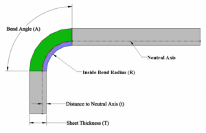
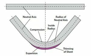
The K-factor in sheet metal bending represents the ratio between the thickness of the metal and an invisible line called the “neutral axis.” When a flat piece of material is bent the inside face of the bend is compressed and the outside part stretches.  This deformation of the material creates a thinning effect in the middle of the bend (similar to how a rubber band thins when stretched).   This neutral axis that divides the metal’s thickness in half  shifts with the bend towards the inside of the bend. The K-factor helps determine how much the metal inside the bend compresses and the metal outside the bend expands, affecting the overall part length.

Knowing the K-factor in addition to the tooling and bend angles is essential to obtaining a correct flange length.  This is because all three effect the expansion and compression of the part in the bend area.

The K Factor is a critical ratio used in calculating the Bend Allowance (amount of stretch).  The formula below shows this relationship between the centerline thickness (t) in the middle of the bend and starting material thickness (MT). 

K=(t/MT)

T = Centerline thickness in bend

MT = Material Thickness


Bend Allowance is the arc length of the neutral axis through the bend. It tells us how much extra length is generated by the bend deforming. If you know the size of your flat material and want to calculate how long the flanges will be after bending, Bend Allowance is what you want.

You can derive the Bend Allowance (BA) by using the K , Bend Radius (R), Bend Angle (A) and Material Thickness using the formula below.

BA=Pi*(R+K*T)*A/180

In this formula:

  • K represents the K-factor.
  • BA is the bend allowance.
  • A is the bend angle.
  • R is the bend radius.
  • T is the material thickness.

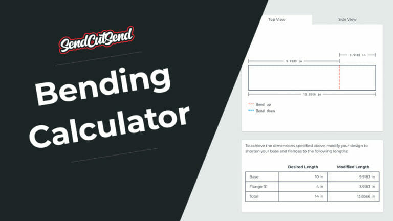
This formula calculates the length of the neutral axis along the bend, which is essential for determining how much extra material length is needed to create a bend accurately. This extra length is then used to apply the bend deduction to the flat pattern of your part.

Bend deduction represents the length of material that should be removed from a flange to account for the stretch (bend allowance) that occurs during the bending process.

The goal of the bend calculation is to predict the amount the material will stretch, reduce that amount of material from the part before the bending so that during the stretching process the part elongates to the final desired length.

Bend Deduction = 2 × OSSB – BA

OSSB = Outside Setback

BA = bend allowance

Bending specifications per material

Material Thickness K Factor Bend Deduction @ 90° Effective Bend Radius @ 90° Die Width Min Formed Flange Length @ 90°
1075 Blue Temper Steel .015″ N/A N/A N/A N/A N/A
2024 T3 Aluminum .025″ N/A N/A N/A N/A N/A
4130 Chromoly .050″ .38 .0945″ .050″ .472″ .302″
.063″ .41 .1065″ .050″ .472″ .308″
.125″ .43 .2050″ .090″ .984″ .723″
.190″ .37 .3240″ .125″ .984″ .782″
.250″ .36 .4335″ .170″ 1.575″ 1.367″
5052 Aluminum .040″ .45 .062″ .024″ .472″ .286″
.063″ .42 .096″ .035″ .472″ .303″
.080″ .43 .115″ .050″ .472″ .313″
.090″ .37 .142″ .032″ .472″ .326″
.100″ .40 .191″ .125″ .630 .463″
.125″ .44 .216″ .125″ .630″ .476″
.187″ .43 .356″ .250″ .984″ .798″
.250″ .42 .442″ .250″ 1.575″ 1.371″
.375″ N/A N/A N/A N/A N/A
.500″ N/A N/A N/A N/A N/A
6061 Aluminum .040″ N/A N/A N/A N/A N/A
.063″ N/A N/A N/A N/A N/A
.080″ N/A N/A N/A N/A N/A
.125″ N/A N/A N/A N/A N/A
.250″ N/A N/A N/A N/A N/A
.375″ N/A N/A N/A N/A N/A
.500″ N/A N/A N/A N/A N/A
7075 Aluminum .125″ N/A N/A N/A N/A N/A
.190″ N/A N/A N/A N/A N/A
.250″ N/A N/A N/A N/A N/A
ABS .125 N/A N/A N/A N/A N/A
.187″ N/A N/A N/A N/A N/A
.250″ N/A N/A N/A N/A N/A
Acrylic .118″ (all colors) N/A N/A N/A N/A N/A
.177″ (clear) N/A N/A N/A N/A N/A
ACM .118″ (black, white, brushed) N/A N/A N/A N/A N/A
.236″ (black, white) N/A N/A N/A N/A N/A
AR400 .250″ N/A N/A N/A N/A N/A
AR500 .119″ N/A N/A N/A N/A N/A
.187″ N/A N/A N/A N/A N/A
.250″ N/A N/A N/A N/A N/A
.375″ N/A N/A N/A N/A N/A
.500″ N/A N/A N/A N/A N/A
Baltic Birch Plywood .125″ N/A N/A N/A N/A N/A
.250″ N/A N/A N/A N/A N/A
.354″ N/A N/A N/A N/A N/A
.472″ N/A N/A N/A N/A N/A
Brass .040″ .38 .074″ .040″ .472″ .292″
.063″ .38 .105″ .040″ .472″ .308″
.125″ .38 .205″ .060″ .630″ .471″
.187″ .38 .324″ .095″ .984″ .782″
.250″ .38 .424″ .130″ 1.575″ 1.362″
Carbon Fiber .040″ N/A N/A N/A N/A N/A
.063″ N/A N/A N/A N/A N/A
.079″ N/A N/A N/A N/A N/A
.118″ N/A N/A N/A N/A N/A
Chipboard .063″ N/A N/A N/A N/A N/A
Copper .040″ .34 .081″ .052″ .472 N/A
.063″ .36 .099″ .024″ .472″ N/A
.125 .34 .205″ .050″ .630″ N/A
.187″ .36 .320″ .118″ .984″ N/A
.250″ .33 .430″ .140″ 1.575″ N/A
Cork (Gasket Grade) .063″ N/A N/A N/A N/A N/A
.125″ N/A N/A N/A N/A N/A
Delrin .125″ N/A N/A N/A N/A N/A
.250″ N/A N/A N/A N/A N/A
G10/FR-4 .063″ N/A N/A N/A N/A N/A
.125″ N/A N/A N/A N/A N/A
.250″ N/A N/A N/A N/A N/A
.375″ N/A N/A N/A N/A N/A
G90 Steel .030″ .38 .0610″ .045″ .472″ .286″
.036″ .38 .0730″ .045″ .472″ .298″
.048″ .38 .0860″ .045″ .472″ .298″
.059″ .36 .1120″ .063″ .472″ .311″
.074″ .40 .1290″ .063″ .472″ .320″
Hardboard .125″ N/A N/A N/A N/A N/A
HDPE .250″ N/A N/A N/A N/A N/A
.375″ N/A N/A N/A N/A N/A
.500″ N/A N/A N/A N/A N/A
LE Phenolic Linen .125″ N/A N/A N/A N/A N/A
.250″ N/A N/A N/A N/A N/A
.375″ N/A N/A N/A N/A N/A
MDF .125″ N/A N/A N/A N/A N/A
.250″ N/A N/A N/A N/A N/A
.375″ N/A N/A N/A N/A N/A
.472″ N/A N/A N/A N/A N/A
Mild Steel .030″ .38 .0610″ .045″ .472″ .286″
.048″ .38 .0860″ .045″ .472″ .298″
.059″ .36 .1120″ .063″ .472″ .311″
.074″ .40 .1290″ .063″ .472″ .320″
.104″ .34 .1815″ .063″ .630″ .459″
.119″ .38 .1955″ .063″ .630″ .466″
.135″ .32 .2440″ .100″ .984″ .742″
.187″ .36 .3225″ .125″ .984″ .781″
.250 .36 .4215″ .150″ 1.575″ 1.361″
.375″ N/A N/A N/A N/A N/A
.500″ N/A N/A N/A N/A N/A
Polycarbonate .118″ .33 0.1950″ 0.040″ 0.472″ 0.368″
.177″ .33 0.2960″ 0.085″ 0.984″ 0.798″
.220″ .33 0.3670″ 0.100″ 1.575″ 1.389″
304 Stainless Steel .030″ .36 .0785″ .080″ .472″ .294″
.048″ .36 .1045″ .080″ .472″ .307″
.060″ .34 .1185″ .070″ .472″ .314″
.074″ .36 .1370″ .075″ .472″ .324″
.100″ .36 .2230″ .187″ .984″ .732″
.125″ .38 .2400″ .150″ .984″ .740″
.187″ .36 .3285″ .130″ .984″ .784″
.250″ .36 .4620″ .225″ 1.575″ 1.381″
.375″ N/A N/A N/A N/A N/A
.500″ N/A N/A N/A N/A N/A
316 Stainless Steel .060″ .34 .1185″ .070″ .472″ .314″
.125″ .38 .2400″ .150″ .984″ .740″
.187″ .36 .3285″ .130″ .984″ .784″
.250″ .36 .4620″ .225″ 1.575″ 1.381″
Titanium Grade 2 .040″ .38 .0790″ .045″ .472″ .294″
Titanium Grade 5 .040″ N/A N/A N/A N/A N/A
.060″ N/A N/A N/A N/A N/A
.125″ N/A N/A N/A N/A N/A
.187″ N/A N/A N/A N/A N/A
.250″ N/A N/A N/A N/A N/A
UHMW .375″ N/A N/A N/A N/A N/A
.500″ N/A N/A N/A N/A N/A

Start your first SendCutSend project today!

Upload your CAD design or use our parts builder and get a free instant quote on your custom laser cut parts, all delivered to your door in a matter of days.
No CAD File? No Problem! Send your sketch or template to our Design Services team. Starting at $49.

We proudly use hardware by PEM

Flush stud, M8 x 1.25, .472" Zinc plus Clear Chromate

Aluminum: 5052, 6061, 7075 Steel: Mild

SKUFH-M8-12
Thread SizeM8 x 1.25
Hole size in sheet (+0.003/-.0.000).315″
Minimum sheet thickness0.94″
Maximum sheet thickness.347″
Fastener materialSteel
Minimum distance hole C/L to edge0.378″
When determining the distance between two or more fasteners, you can calculate the distance by the formula, C/L to edge + 1/2 the diameter of the second mounting hole..567″
Recommended panel materialSteel/Aluminum
Coating typeZinc
Length.472″
Aluminum material ranges (5052, 6061, 7075)0.100″-0.250″
Steel material ranges (CRS, HRPO, HR)0.104″-0.250″

Get an Instant Quote for Waterjet Cutting

We proudly use hardware by PEM

Flush Standoff, 4-40, .250" Zinc plus Clear Chromate

Aluminum: 5052, 6061, 7075 Steel: Mild, G30

SKUSO-440-8
Thread Size4-40 x .250″
Hole size in sheet (+0.003/-.0.000).168″
Minimum sheet thickness0.040″
Maximum sheet thickness.125″
Fastener materialSteel
Minimum distance hole C/L to edge0.230″
When determining the distance between two or more fasteners, you can calculate the distance by the formula, C/L to edge + 1/2 the diameter of the second mounting hole..345″
Recommended panel materialSteel/Aluminum
Coating typeZinc
Length.250″
Aluminum material ranges (5052, 6061, 7075)0.040″-0.125″
Steel material ranges (CRS, HRPO, HR)0.048″-0.119″

We proudly use hardware by PEM

Flush Standoff, 4-40, .250" Passivated

Stainless Steel: 304, 316

SKUSO4-440-8
Thread Size440
Hole size in sheet (+0.003/-.0.000).166″
Minimum sheet thickness0.04″
Maximum sheet thickness.125″
Fastener material400 Stainless Steel
Minimum distance hole C/L to edge0.230″
When determining the distance between two or more fasteners, you can calculate the distance by the formula, C/L to edge + 1/2 the diameter of the second mounting hole. Example shown with x2 of the same hardware..345″
Recommended panel materialStainless Steel
Coating typePassivated
Length.250″
304 Stainless Steel material ranges0.048″-0.125″
316 Stainless Steel material ranges0.060″-0.125″