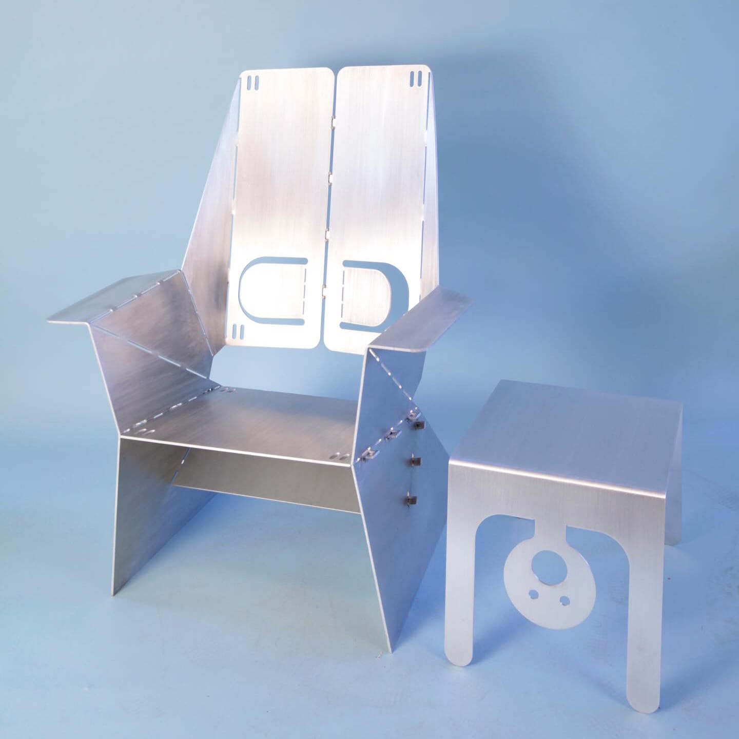
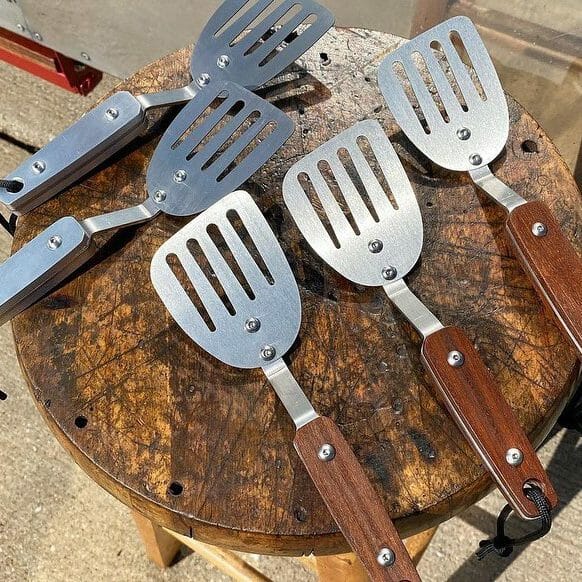
SendCutSend offers plastic and sheet metal bending and fabrication on flat sheet metal and CNC routed parts with no minimum quantity.
Accurate, repeatable bends
Formed to match your design intent with consistent results across parts and batches.
Fast Turnarounds
Bending is done in-house, adding minimal time to standard production.
Simple, all-in-one workflow
Upload your flat pattern, set your bends, and get instant pricing.
“SCS beats my local shops in every dimension… Did some bends my usual shop would have baulked at.”
Rzad Design
Available materials for Bending
We offer CNC bending for a wide range of materials including aluminum, brass, chromoly, copper, steel, mild steel, polycarbonate and titanium.
For a full list of materials and available thicknesses, please visit our materials page.
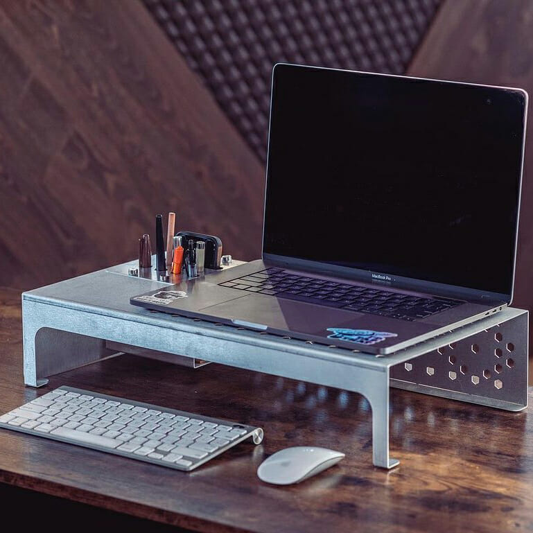
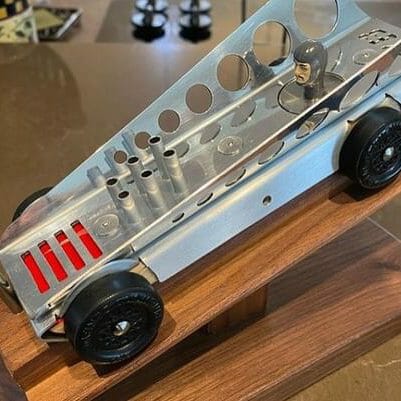
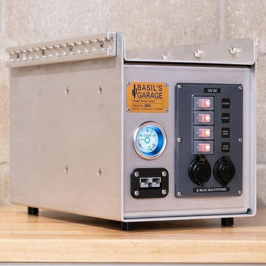
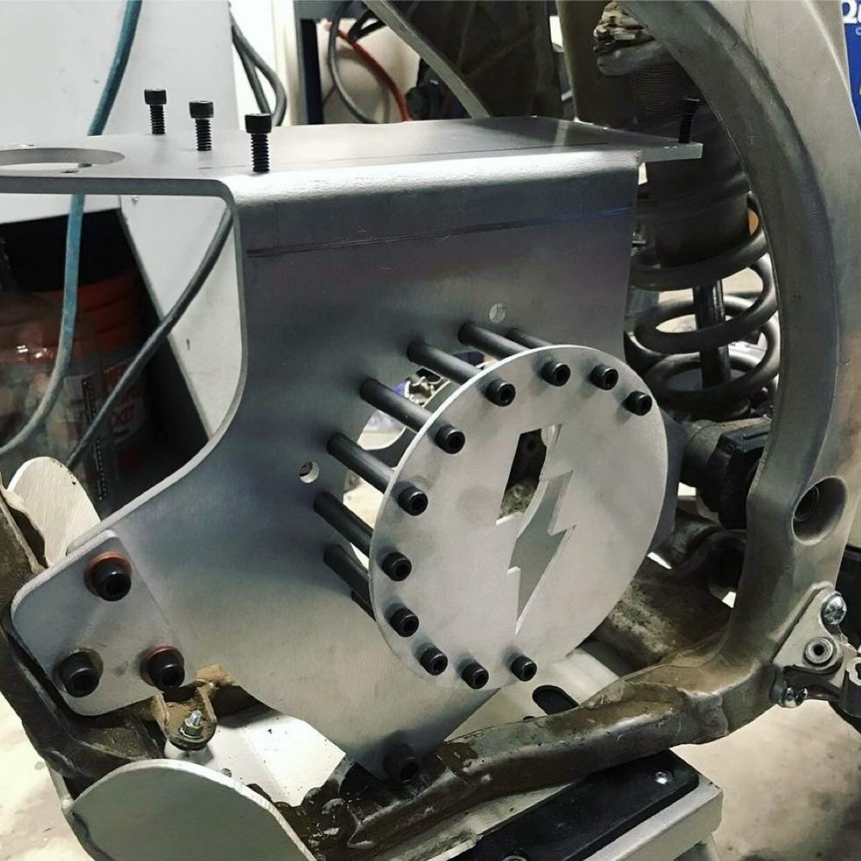
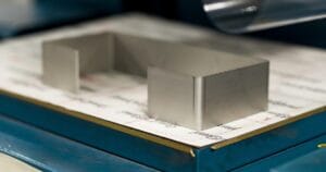
One step to a finished part Built to take abuse Looks as good as it performs
Working in CAD? Import our gauge tables for Autodesk Fusion or SolidWorks to apply the latest specifications automatically.
File setup
Upload a 2D vector file (.dxf, .dwg, .ai, .eps) or a 3D file (.step, .stp). You’ll confirm bend angles and flange orientations in a 3D preview during checkout.
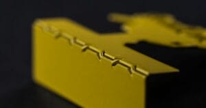
Bend relief notches reduce stress on inner radii and prevent corner tearing or bulging. This is critical for polycarbonate, which cracks without adequate relief.
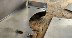
We can bend irregular flange shapes, but we need a flat surface parallel to the bend. Add break-off tabs to create a straight reference edge, then remove them after you receive your part.
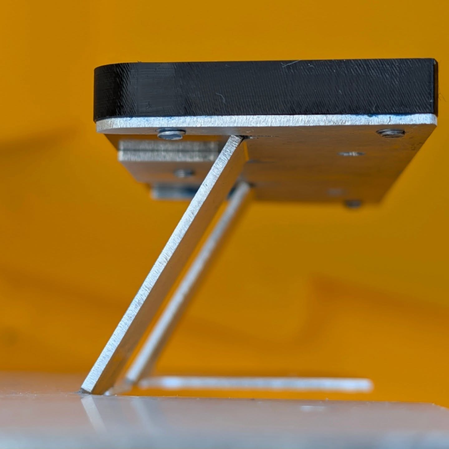
We form sheet metal and plastic with air bending, where the punch presses the material into a V-die without bottoming out. This affects bend radii and is especially important to understand for polycarbonate.
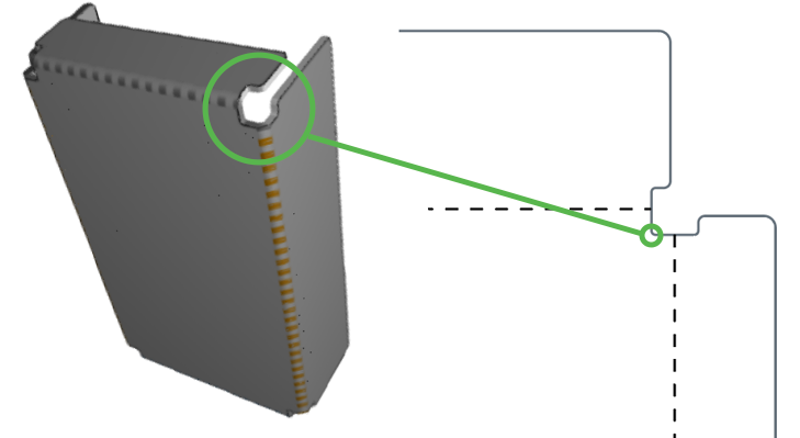
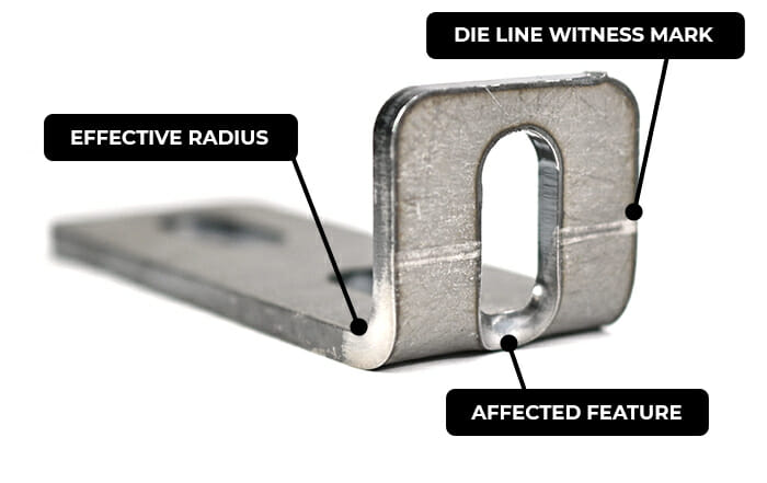
Die lines are witness marks left where the tooling makes contact with your part during forming. Cut features that fall within die lines or the bend area will distort as the material stretches.
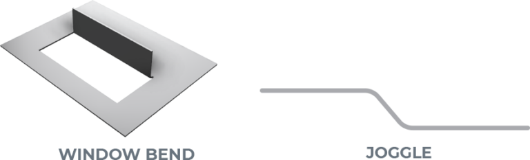
Combined lines: Bends on a common axis must be joined. If they’re separate, each will be treated as an individual bend.
Intersecting bends: We can’t bend intersecting lines that don’t have separate flanges.
Incomplete bends: A bend must extend all the way across the area being bent. We can’t form partial bends.
Insufficient contact: Flanges need to meet the minimum flange length for at least ~50–60% of the bend’s length on both sides to provide enough press brake support. Thicker materials (.187″–.250″) need more contact.
Insufficient or missing bend relief: Certain designs require bend relief to avoid damage to the part. Without proper relief, a part cannot be bent accurately. This is critical for polycarbonate parts since the material is prone to cracking.
Additional bending resources
If you’re designing parts for powder coating, these resources may help:
File is in a format that we accept (2D: .dxf, .dwg, .ai, .eps; 3D: .step or .stp)
All holes and cutouts are at least 50% material thickness for laser cut parts
All holes and cutouts are no less than 0.070” for most waterjet cut parts
All holes and cutouts are no less than 0.125” for all CNC routed parts
File is built at a 1:1 scale, preferably in inch or mm units
2D files: all objects on the same layer, text converted to outlines, no open contours, all shapes united or merged, floating interiors bridged or stencilized
3D files: single solid sheet metal body, uniform thickness with a face at every edge, modeled at stock thickness with matching bend specs
All stray points, duplicate lines, empty objects and text areas have been removed
SendCutSend reviews
Customers love getting their sheet metal parts from us
Great service. The process of ordering is great and they ship your parts to you quick. I’ll be sure to use them in the future.
Posted on Google
Mike Greene
June 20, 2026.
It’s all in the name. Simple and effective. Couldn’t be happier
Posted on Google
Franz Krachtus
June 19, 2026.
This was my first order with SendCutSend, and Darren went above and beyond to help me.
I had a technical issue, and after chatting with Darren, he figured out that the problem was caused by how I had prepared/exported my file. Darren patiently helped me troubleshoot the artwork, checked my revised upload, and even pointed out one small area that needed to be adjusted to cut out properly.
I'm not used to this type of service. This is not how customer service is supposed to work in 2026. Let me get frustrated with an AI chatbot and never return my inquiry! Darren genuinely cared and made sure my project turned out right.
The final piece came out beautifully and I'm so happy with SendCutSend. I can't wait to create more art pieces with them.
Posted on Google
Logan Wesley
June 19, 2026.
Best service oat got my custom sheet metal stuff made rlly well would recommend they are crazy fast. SUPER lowwww prices compared to other similar services deff gonna get stuff from them again.
Posted on Google
Oliver Strong
June 19, 2026.
Only downside SendCutSend is one more reason my wife doesn't think I need my own CNC plasma solution.
Posted on Google
Erik Newman
June 19, 2026.
My first try with SendCutSend: It's been hard to get local cutters to do small jobs, I'll use SCS again. Easy interface, delivered before the promised date. Parts are good, price is good.
Posted on Google
T R
June 18, 2026.
Great experience with making some revisions to my order. Julie walked me through the process of uploading my changes quick and efficiently.
Posted on Google
Aresch Panah
June 18, 2026.
Very precise and great prices!
Posted on Google
Logan Power
June 18, 2026.
Quality product, fast shipping and proactive communication. Will be using moving forward.
Please note: Pricing examples on our website are provided as general estimates and may not always reflect current prices. While we strive to keep these examples accurate, uploading your file is the best way to see instant current pricing.
Start your first SendCutSend project today!
Upload your CAD design, or try one of our customizable part templates to get instant pricing on your custom laser cut parts. All delivered to your door in a matter of days.