| Adobe Illustrator | .ai |
| AutoCAD | .dxf, .step, .stp |
| CorelDraw | .eps |
| Fusion | .dxf, .step, .stp |
| Inkscape | .eps |
| SolidWorks | .dxf, .step, .stp |
If you design in non-CAD software (Illustrator, Inkscape, CorelDraw), send us the native .ai or .eps file. We’ll handle the conversion.
What we can’t accept: STL (mesh) files, or raster files like JPEG, TIFF, PNG, or BMP.
We have tutorials to help you convert your art to a vector format in Adobe Illustrator and Inkscape.
A flat part is usually a 2D vector file. A bent or formed part is a 3D STEP file. Two of these rules apply to everything. After that, follow the list for your file type.
These rules apply to every part we cut, no matter the material or method.
Build your file at the exact size you want it cut. We don’t adjust based on written dimensions in the drawing, those are ignored by our system. Inch units are preferred. Mm is fine if you keep it consistent between your file and your quote inputs. We don’t support cm or meter units.

Strip out dimensions, notes, borders, title blocks, and any other annotation. The only geometry we need is the cut path.
“Student Version” lettering from SolidWorks is auto-ignored, you don’t need to remove it.

Active text boxes won’t cut. Convert text to outlines (Illustrator) or explode/expand (CAD) before exporting. If you can hover your cursor over the text and edit it, it’s still active.

Letters like O, A, or B have internal cutouts that fall out without bridges. Same goes for any “donut” shape. Add bridges, or stencilize the design, so floating pieces stay attached. Minimum bridge width varies by material, check the material specs for your stock.

Every cut path must form a closed shape. If your shape stops, so does the cutter. View your file in outline or wireframe mode to spot open contours.

Two parts sharing a line, or overlapping lines inside one part, won’t cut correctly. Check in outline or wireframe view and clean up overlaps.

All cut-path geometry should be on the same layer. Move guides, construction lines, and unused objects off the cut layer or delete them.
3D files are for parts with bends or forms. These rules keep a STEP file from erroring out on upload.
Your STEP/STP file should contain a single, solid sheet metal body, even if you plan to order a non-metal sheet material. Files with multiple bodies or assemblies won’t upload. If your design has more than one body, save each into its own file and upload them separately.
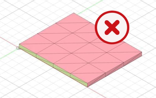
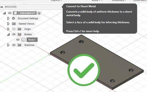
Set the part up using sheet metal tools, even for non-metal sheet stock. Extruded bodies and mesh bodies won’t upload. Convert an extruded body to sheet metal before exporting. (Mesh/STL files aren’t accepted at all.)
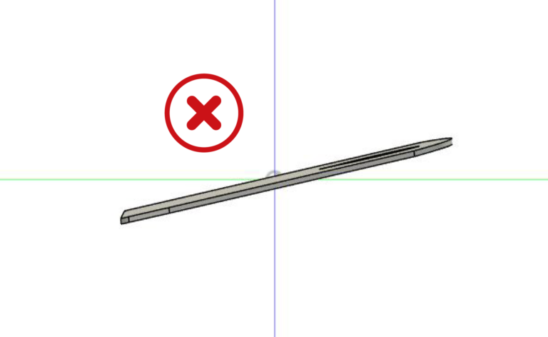
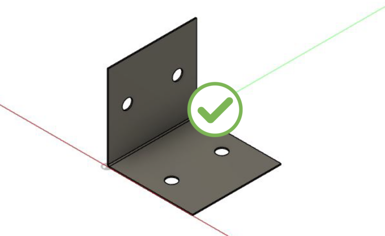
The model needs one stationary entity, like the base of a formed part, aligned flat to a plane in the drawing space. Bodies angled relative to a plane may not process accurately. Parts pulled out of an assembly often keep a tilted orientation, so check and reorient before exporting.
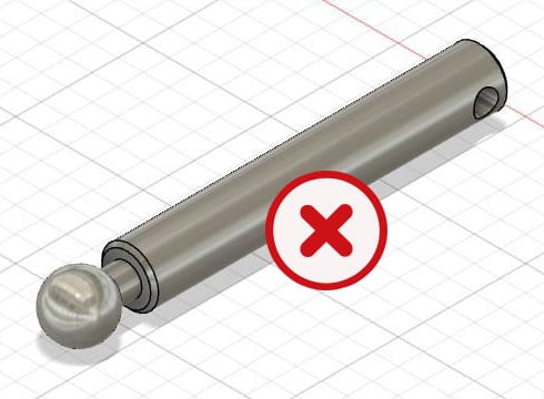
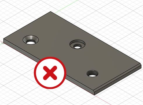
For sheet and plate we cut 2D full depth only. Tapered edges, partial-depth features, or modeled countersinks and counterbores can throw an error or get read as a billet part that needs CNC machining. Keep thickness uniform with a face at every sheet edge. For hole services (countersinking, dimple forming, hardware, tapping), model simple through-holes and add the service in the app after upload.
Model the part at the thickness you’ll order, using a sheet metal rule that matches the stock you’ll select. This holds whether or not you’re bending, so the parts you get back match the parts you designed.
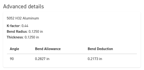
If the part is bent, your sheet metal body must use our K-factor and bend radius for the material, or it can throw an open-contours error. The values live in the Bending Calculator. See the bending guidelines for full bend guidance.
Exports sometimes come out empty or malformed, so check the final file. If your upload shows dimensions of 0″ x 0″, the part probably wasn’t selected when you exported, or the file is a 2D surface with no 3D geometry. Reselect the part and export again, or send a 2D vector format instead.
| Method | Materials |
|---|---|
| Laser Cutting | Metals, acrylic, and select boards |
| Waterjet Cutting | Composites (carbon fiber, G10/FR-4, phenolic), rubber, and foam |
| CNC Routing | ACM, plastics, and woods/boards |
This is a guide, not a hard rule. Thickness can move a material from one machine to another, and a few materials (like Delrin and MDF) appear under more than one method at different thicknesses. Each material’s page lists the method and the exact specs for that stock. For the full list of materials and thicknesses, see our materials page.
Once you know which machine cuts your material, these are the rules that apply.
The pierce or tool entry needs a certain amount of room. Holes smaller than the minimum will distort, char, or fail to cut.
| Method | Minimum hole/cutout |
|---|---|
| Laser Cutting | At least 50% of material thickness |
| Waterjet Cutting | .070″ for most materials (varies by material, check material specs) |
| CNC Routing | .125″ (bit diameter), all hole |
For laser and waterjet, the exact minimum changes with the material and thickness. The current values for every stock we carry live on each material’s page.
Sharp internal corners aren’t possible. Every method leaves a radius wherever the tool or stream enters a corner. Design fillets in from the start.
| Method | Minimum internal radius |
|---|---|
| Laser Cutting | Approximately the kerf width (very small) |
| Waterjet Cutting | .032″ (stream diameter) |
| CNC Routing | .063″ (radius of 0.125″ bit) |
The CNC router uses 2D flatbed machining. It cannot do v-grooves, 3D contours, partial-depth cuts, double-sided cuts, or counterbores. If you need threads or countersinks, those are separate services. See our tapping and countersinking guidelines.
Every routed part gets small tabs left on the edges to hold it in place during cutting. Tabs are about 0.1875″ wide, with depth equal to half the material thickness. They sand off easily and won’t affect your final design. To place them, we need at least 0.400″ between nodes on your part edge. Most files meet this when exported without excess nodes.
Because the bit is round, interior corners on routed parts always have a 0.063″ radius. A square peg won’t seat cleanly in a square pocket. If a slot or pocket needs to mate with a square edge, use a dogbone fillet, a small over-cut at each interior corner that opens the radius enough for the square part to seat. Standard chamfers and fillets don’t solve this. Dogbones do.
Parts with too much material removed (grills, grates, perforated patterns) are likely to shift or break during cutting. Keep material removal under 50%. Designs above that may be rejected.
Routed edges can have small witness marks, steps, and light burning from the cutting process. This is normal for the router and won’t affect the function of your part.
Part size limits depend on the material and method. The full chart lives on our min/max part size page.
CNC routing has the tightest limits worth calling out here:
If you want multiple copies of the same part, upload one part per file and set the quantity at checkout. You’ll get a quantity discount, and our system nests your parts for production automatically. This is simpler than building a nested file yourself.
You can put multiple different parts in one file if all parts use the same material and thickness, all geometry meets our sizing requirements for that material, and you’re exporting a 2D file format (.dxf, .dwg, .eps, .ai). We can’t accept pre-nested STEP/STP files. If you need multiple bodies in a 3D file, see our Assembly Guidelines.

If any part needs bending, tapping, countersinking, dimple forming, or hardware, submit it as its own file. Pre-nesting these slows production and can cause errors.
Sharing a cut path between two parts doesn’t account for kerf, beam width, tooling diameter, or waterjet stream width. The actual gap between common-nested parts runs 0.006″ to 0.012″ depending on material, so your “precision fit” will end up loose. If you want a slip fit, design the inner part smaller (by the cut tolerance of your material) and place it in a separate file or a different area of the same file. Files with common-line nesting will be returned for revision, which delays your order.

If you have multiple identical parts in one file, we can’t guarantee which side ends up as the top. That matters for materials with distinct top and bottom surfaces (ABS, brushed ACM, mirrored acrylic, and hardboard). If you need mirrored parts with a specific top side, save each version into its own file.

Intricate patterns can burn or warp. Our fiber lasers cut fine detail well, but long total cut time on dense designs can scorch edges or warp thin material. If you see burn marks on a sample, thickening the joining lines in the pattern usually fixes it.
For tips on keeping a dense part affordable, see our pricing page.
Exporting a 2D file from a 3D program (Fusion, SolidWorks) can leave 3D faces or surfaces in the file. Save your design in STEP/STP format instead, or follow our export tutorials for a clean 2D file.
Third-party converters often produce files that look right but don’t process correctly. Avoid converters. Export directly from your CAD or design program in a format we accept.
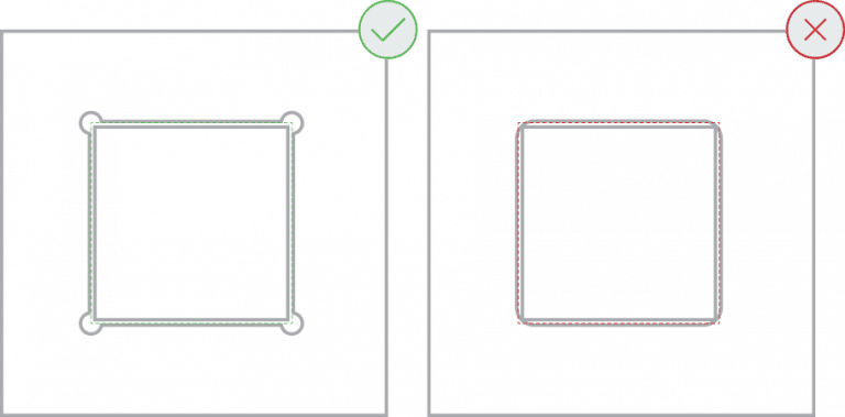
Usually a sheet metal rule mismatch, or tapered or rounded bend reliefs. Use square bend reliefs (or export a DXF instead), and match your bend radius and K-factor to our values. See the 3D file requirements above.
The part wasn’t selected before export, or the file is a 2D surface with no 3D geometry. Reselect the part and export again. See the 3D file requirements above.
Before you upload your design, take a look at our file preparation guidelines. They cover everything you need to know including file setup, sizing, supported formats, and tips for keeping costs down, so you can get the best results from your custom parts.
2D: .DXF, .DWG, .EPS, .AI.
3D: .STEP, .STP. We can’t accept STL (mesh) or raster files (JPEG, PNG, etc.).
We route by material. Most metals go on the laser, composites and rubber and foam go on the waterjet, and ACM, plastics, and woods go on the router. Your material’s page lists the method and specs. Thickness can change the routing, so check the material page when in doubt.
The cutter has to pierce the material to begin a hole. Thicker material needs a wider pierce. Specific minimums per material and thickness live on each material’s page.
You can, but it’s not the best practice. Upload one part per file and adjust the quantity at checkout. You’ll get a quantity discount and faster processing.
The gap between common-line nested parts runs 0.006″ to 0.012″ depending on material, so you can’t get a precision fit that way. It also leaves pierce marks and lead-in lines where you don’t want them.
No. We add fixturing tabs automatically. They’re about 0.1875″ wide, sand off easily, and won’t affect your design.
Not by default. Interior corners on routed parts have a 0.063″ radius from the bit. Use dogbone fillets at the corners to open them up for a square mate.
Keep material removal under 50%. Beyond that, parts can shift or warp during cutting and may be rejected.
We accept .ai, .dxf, .dwg, .eps, .stp, and .step
Customize one of our simple parts templates
