If you have a design in the form of a JPEG or PNG that you found or purchased online which you want to turn into a laser cut part, you will first need to convert that design to a different file type. Namely, a vector file.
Before we get into exactly how this conversion can be made, it’s very important to remember that whatever you do, do not use an online file converter. This may seem like the fastest, simplest solution, but online file converters have a nasty habit of producing the lowest quality files that are the most difficult to process. It’s better to just convert your own raster file to a vector file manually.
We promise this is actually much easier than it sounds! In this article, we’ll walk you through a step by step process to vectorizing your files using Inkscape, a completely free and open source graphic design software.
Why Are Vector Files Required for Laser Cutting?
We require vector files for laser cutting because in the background, vector files are graphed with geometric shapes, which act as a set of coordinates for the laser. These coordinates are understood by the laser because they are determined through a set of mathematical equations, unlike raster files which are just graphic images, or pixels. A raster file’s clarity depends on its resolution and it doesn’t scale correctly, so the laser won’t be able to “find” the true edge lines of your part. It will reject all files that are not vectors.
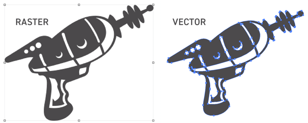
You can see the difference between how these two file types appear in most software in the image below. The raster file uses colored pixels to display different images, but since CNC machining software doesn’t differentiate between colors and pixels, it only sees the boundaries of the part being where the pixels stop. The raster image, then, is seen as just a square piece of metal. On the vector file, you can see each of the small “points” or nodes defining the edges of the design. These nodes act as destination points for the laser, telling it where to go next and what edges to cut. Well-designed vector files will have a clean image with a minimal amount of nodes, producing a smooth laser cut edge and a high quality part.
If you still need some help understanding why you need to convert files for laser-cutting, check out our article, “Why We Require Vector Files for Laser Cutting.” And if you use Adobe Illustrator for your design needs, make sure you use our guide to Vectorizing Raster Images in Adobe Illustrator.
How to Vectorize an Image in Inkscape?
1. Import your raster image
Create a new document in Inkscape and import your raster image. If you use the “edit path by nodes” tool (F2), you’ll see that we have no nodes to select. You’ll also notice the edges are a little fuzzy or pixelated. We can fix that!

2. Trace bitmaps
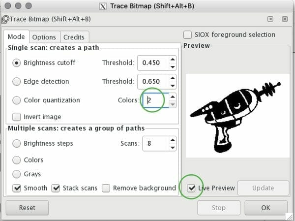
With your raster image selected, go to the Path menu and select Trace Bitmap (Shift+Alt+B).

When you open the Trace Bitmap dialog, you will see several options for bitmap tracing: brightness cutoff, edge detection, and color quantization. Each of these options will produce a unique result based on what the tracer is detecting in your image and what parameters it has been given.
The “brightness cutoff” option takes the sum of red, green, blue, and gray values in a pixel to determine if it should be output as white or black. Increasing the threshold will decrease the values the tracer needs to determine if a pixel should be black, making the output “image” darker.
“Edge detection” uses a specific algorithm to find isoclines in your file that have similar contrast. This output will likely be less similar to your original image, but some of the paths produced may be helpful in adjusting your final design. Adjusting the threshold of this option changes where pixels that are adjacent to high contrast edges are sorted into, changing the detail of the edges detected in the output.
The third option is “color quantization,” which is similar to edge detection in that it identifies isoclines of varying contrast, except the contrast in this situation is a change in color. This tracer finds where the color changes at each edge, regardless of brightness or contrasts, and determines whether that color will be output as black or white. Setting the number of colors to a low number will decrease the number of colors included in the output, creating a simple image. Setting the number of colors to a high number will increase the number of colors the tracer detects, outputting a more detailed, complicated path.
For most laser cutting purposes, you’ll want to select “Color Quantization” and set the number of colors to 2, but play around with this feature to find what yields the best result for your design. You’ll want to adjust the rest of the settings according to your image. Keep an eye on the window that shows what you’re changing as you change it. When you’ve got everything dialed in, click “Update” and “OK”, and close this dialog.
Your image is now a vector object with paths and nodes. You need to delete the original image. It’s hiding behind the traced version. Select your vector object and move it to the side. You can now delete the raster image.

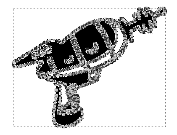
3. Reduce nodes
Select your object with the Edit path by nodes tool (F2) again. Depending on the quality and complexity of your image, you may have an unwanted amount of nodes. You can see that this image most definitely has way too many. We need to get rid of these because the laser follows a map from point to point (node to node). If a path has too many nodes, it will not be usable for manufacturing. If you can simplify the laser’s path, you are going to get better results.
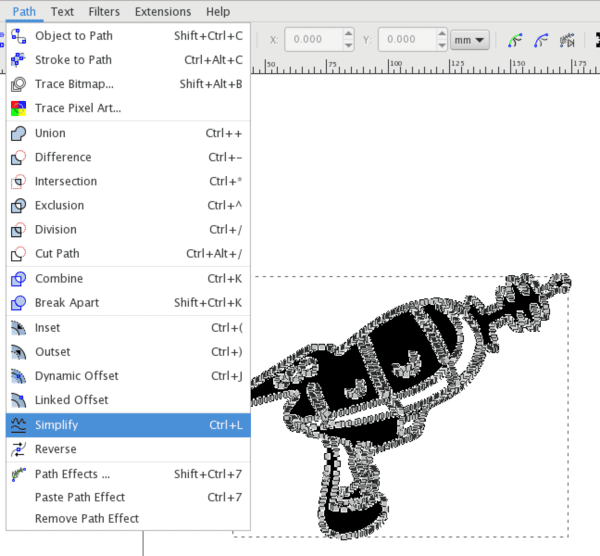
The good news is there is a very simple solution. Select your object and go to the “Path” menu again. Select “Simplify” (CTRL+L). This will reduce the amount of nodes.
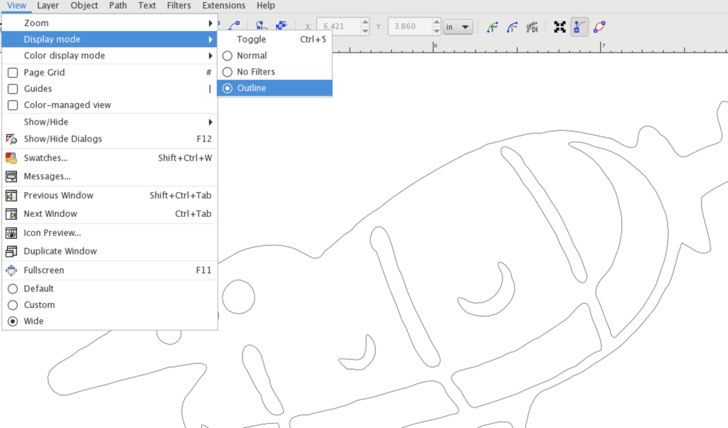
The next thing you’ll want to do is inspect the edges of your object to make sure things are straight and smooth. This again will depend on the quality and complexity of the image you began with. Zoom in tight and view your image in Outline display mode.
The lines for this object are pretty bumpy and jagged. It’s important to clean these up because the laser will cut them exactly as seen here. There are a few ways to do this.
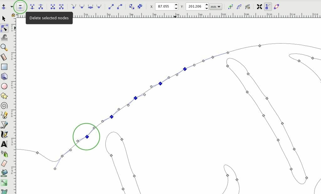
Select your object again with the “edit path by nodes” tool (F2). Along the top you’ll notice there are still a lot of extra nodes. You can select them by shift+clicking the nodes you want to target. They will turn blue once selected. Now, you can click the “delete selected nodes” button in the top toolbar.
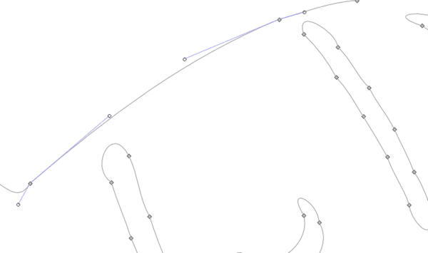
The extra nodes have been removed which resulted in a much smoother curve.
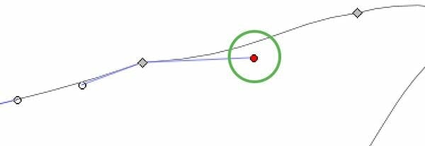
Another way to smooth curves and lines is by adjusting the node handles. Click F2 to activate the “edit path by nodes” tool. Select a node and grab one of the handles. These will turn red when selected. Moving these handles will adjust the curve of the lines attached to that node.
4. Check Size and Scale of Design
Once you’ve finished cleaning up your edges, you’ll want to check the size of your object and make sure it’s to scale. Using the “select and transform objects” tool (F1), select your object. You can scale it up and down by dragging the outer arrows. Holding the CTRL key as you drag will scale your object proportionally. You can also just type in your desired dimensions in the top toolbar. Make sure your dimensions are in inches so it will import to the laser correctly.

Preparing Vector Files for SendCutSend
If you followed this tutorial, you have successfully converted a raster image to a vector file in Inkscape and you’re almost ready to submit your order for laser cutting. This guide showed you how to trace and simplify your design, but now you need to make sure every aspect of the design fits within our design guidelines. Each laser cut part must fit within the size limitations for its material and thickness, and elements on the interior of the design must have appropriate bridging. Be sure to check out the full list of guidelines and check your design one last time.
Once you’ve done that, you’re ready to send your parts off to the laser! Upload your laser cut-ready files and get instant pricing today.
