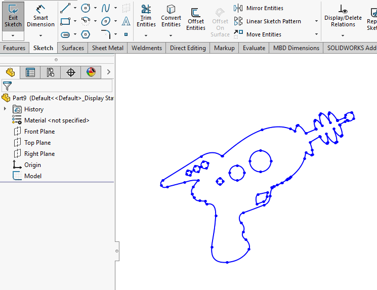
DXF (Digital Exchange Format) files are one of the vector format file types SendCutSend uses to laser cut, waterjet and CNC route our customers’ parts. Making a DXF file for your design can be done in multiple ways, using many different software programs. Here we want to cover how to deal with DXFs in SolidWorks, one of the leading 3D CAD software packages.
SolidWorks is a modeling software for 3D designs, but we need 2D vector files to cut your parts. Saving the whole part as a .DXF will flatten all the outlines for the whole part and complicate the cut. But never fear! You can export the outlined face of the part exactly as it should be cut by following this tutorial.For guidance on how to export a 2D cut pattern from SolidWorks for parts that require SendCutSend’s CNC bending services.
How to Import DXF Files in Solidworks
Often when preparing your design files you need to include existing shapes. These might be logos, uniquely sized or shape holes to mount off-the-shelf parts, or maybe the profiles of other nearby components. Whatever the reason, importing a DXF into your SolidWorks file is a good way to make it happen.
Step 1
Starting the process is simple, select “File-Open” and choose the DXF file you want to import. This will bring up the DXF/DWG Import window.
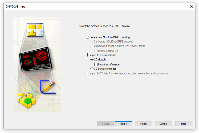
Here you have a few options to choose from. If you’re using the imported geometry in a part to get laser cut, select “Import to a new part as:”, “2D sketch” and leave the “Import as reference” box unchecked.
If you check the “Import as reference” box, you’ll still import the geometry, but it won’t be editable. This may or may not be important to you. In this example, we’ll leave it unchecked to have the most flexibility.
The example we’re showing here is for a 2D sketch, which is the most common form for DXFs, but they can also contain 3D information. If you know your DXF contains 3D data, you can import as “3D curves or model”. We’ll stick with 2D sketch for now, as that’s the most relevant to CNC laser and waterjet cutting your parts.
Click “Next”.
Step 2
This will take you to the Import Settings Window. From here you’ll be able to change the units and select any layers you may or may not want to import.
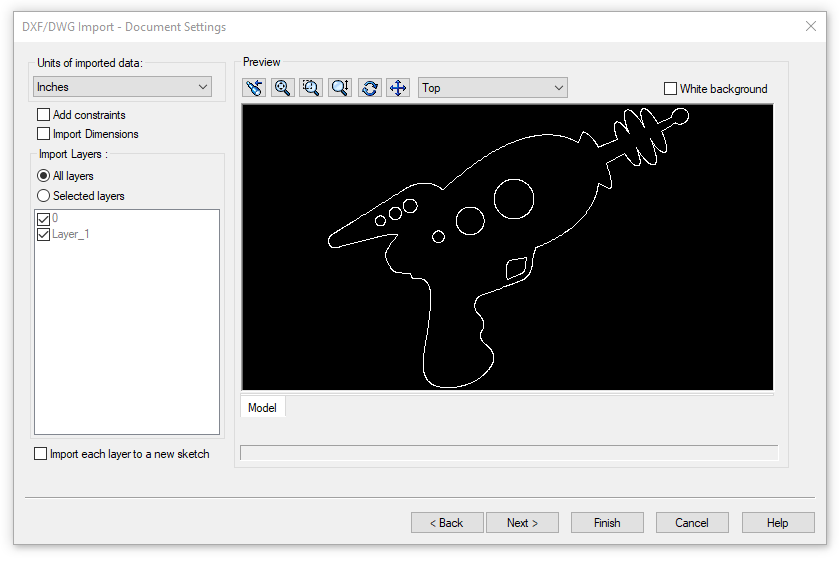
Note: If you’ve left the “Import as reference” box checked in the previous step, a few of these options won’t be available to you, such as “Add constraints” and “Import Dimensions”. You also won’t have the option to select “Next” as this is the last step when importing as reference and you can just click “Finish” instead.
Once you’ve made your selections, click “Next”.
Step 3
In the next window, you’ll have a few more options. Here you can clean up any issues in the geometry, removing unwanted lines or merging points that aren’t quite touching. You don’t have to clean up the geometry here, you can also edit the sketch after you import it. Sometimes that’s easier.
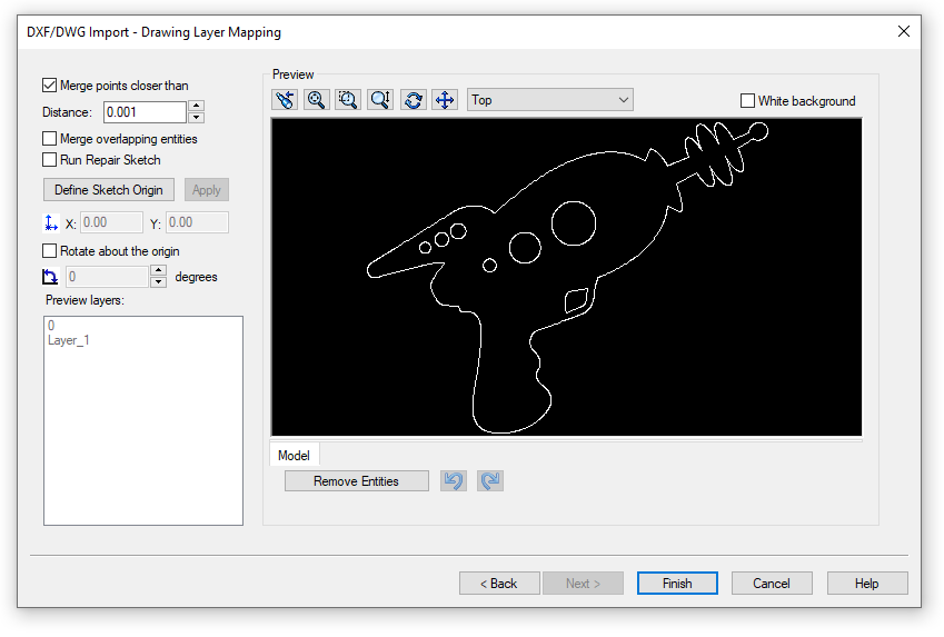
Once you’ve made your selections, click “Finish”.
Step 4
The final results you get will depend on the DXF you started with and the options you selected, but you should now have a new sketch (or multiple sketches). You may be in the “Edit Sketch” mode and need to exit that mode.
From here you can use the sketch however you need to.
Exporting to DXF Files in Solidworks: 3 Methods
There are several methods for creating/exporting a DXF from Solidworks. We’ll go over three simple methods for exporting a single face, exporting a sketch, and exporting a flat pattern as those tend to give the cleanest, most predictable results. Before we go through the steps, be sure you’re set up correctly for the results you want.
Settings
Let’s start with looking at the export settings for DXFs in the System Options. You should only need to do this step once. Check your export settings and make sure they look like this:
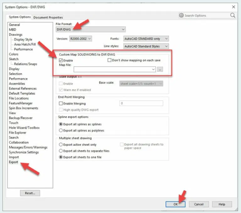
Exporting all splines as splines is ideal.
Method #1 – Exporting a Face
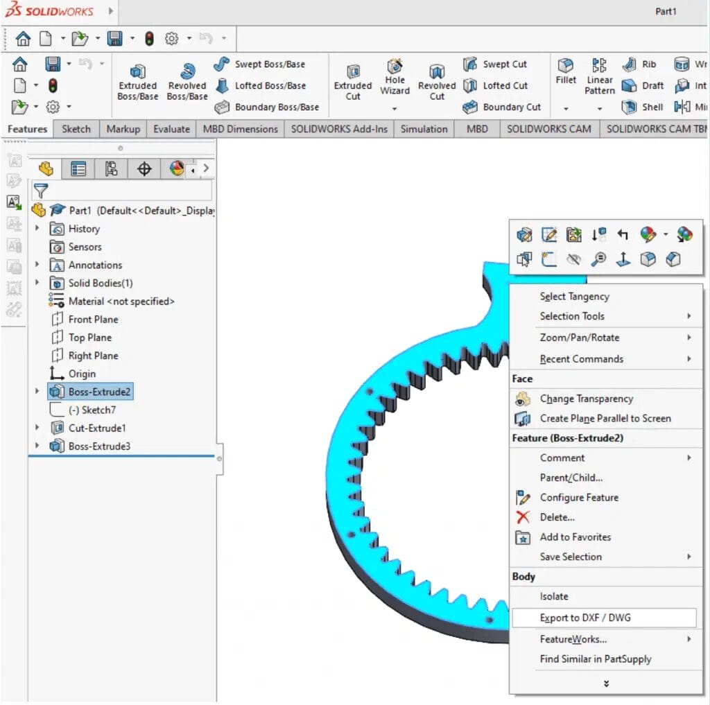
Step 1
From a Part or an Assembly, select the face you want to export. Right-click and select “Export to DXF/DWG.” Be sure the face is flat, curved faces can cause issues. Remember the end result is a 2-dimensional shape to cut from flat stock.
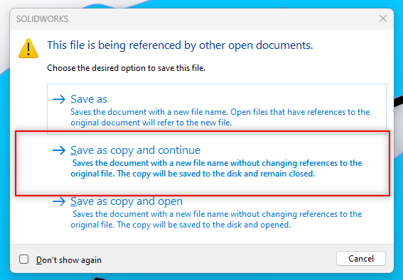
You may see a pop-up asking how you want to save your file. If so, just click “Save as copy and continue.”
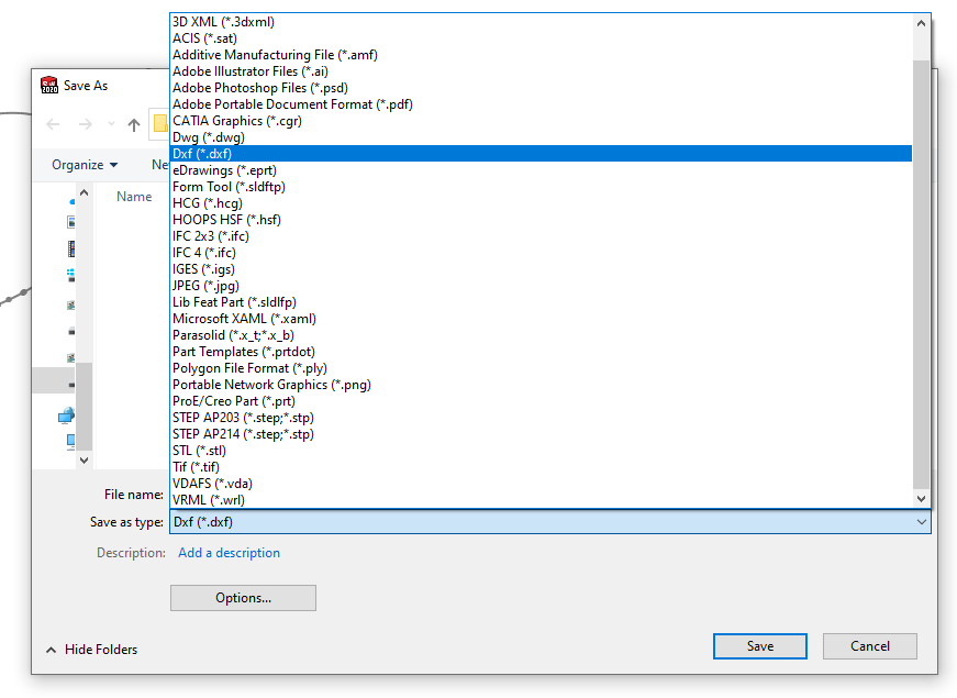
Step 2
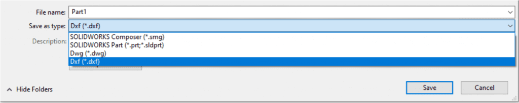
A save dialogue will pop up; name your file and select “DXF” file type.
Step 3
This will prompt a DXF/DWG Output menu to the left. Confirm that only the face of the part is selected, not the whole body. We just need the top-down “outline” view, exactly as you want the laser to cut it. The default settings are usually fine, but if the output preview in the next step doesn’t look right, you may need to cancel the export and adjust some of these settings.
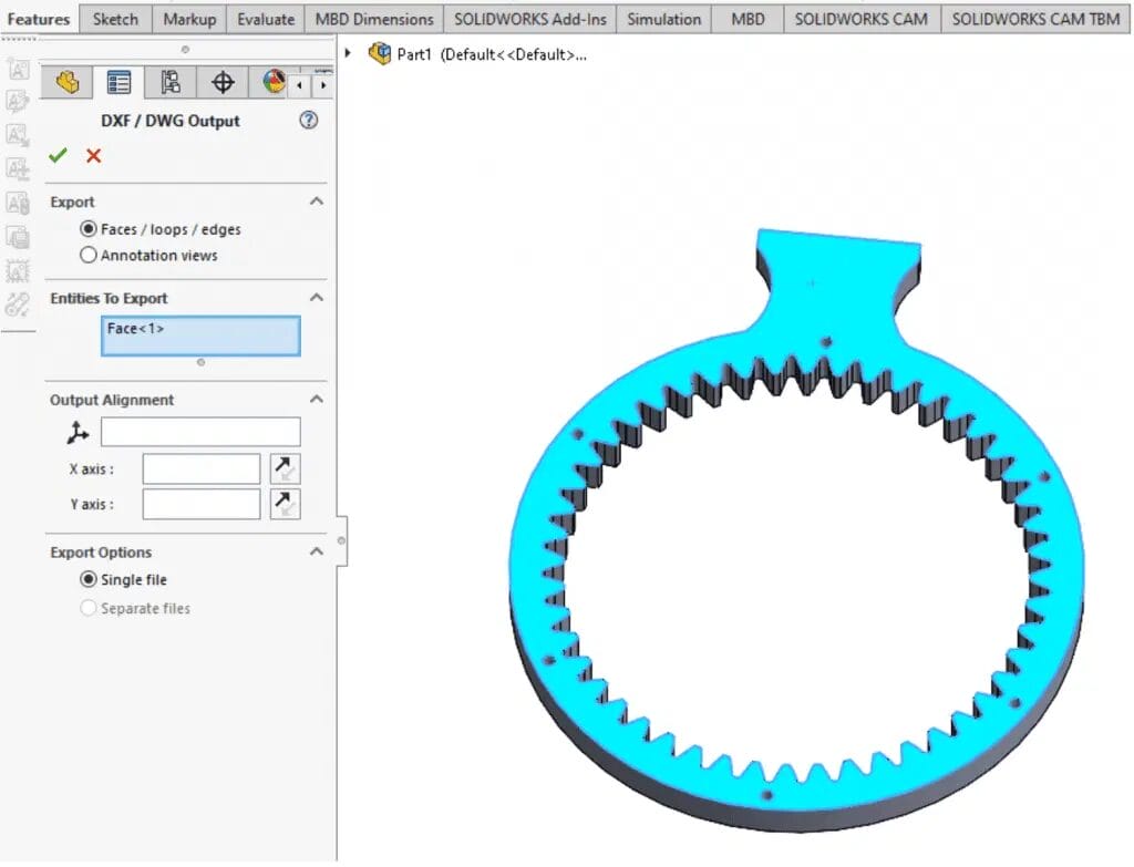
If that looks right, click the “green check mark”.
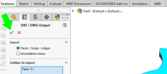
Step 4
A preview of your DXF will appear. If you need to you can remove any unwanted lines here fairly easily by selecting them and clicking the “Remove Entities” button. Be careful not to remove anything you need or leave any open loops. Dashed lines are ok if you’re exporting bend lines. Once everything looks right, click “Save”, and you’re all set!

Method #2 – Export from a Sketch
Step 1
The key to exporting a sketch as a DXF is that the sketch should be the only active feature. If you’ve created a new sketch and that’s the only feature, then you’re good to continue. If you already got a part modeled and the sketch is part of it, you’ll want to copy the sketch to a new empty part.
Step 2
Select “File – Save As”. When the save dialog box appears, choose the location to save, name your file and change the file type to “DXF”. Click “Save” and your file is created. That’s all there is to it.
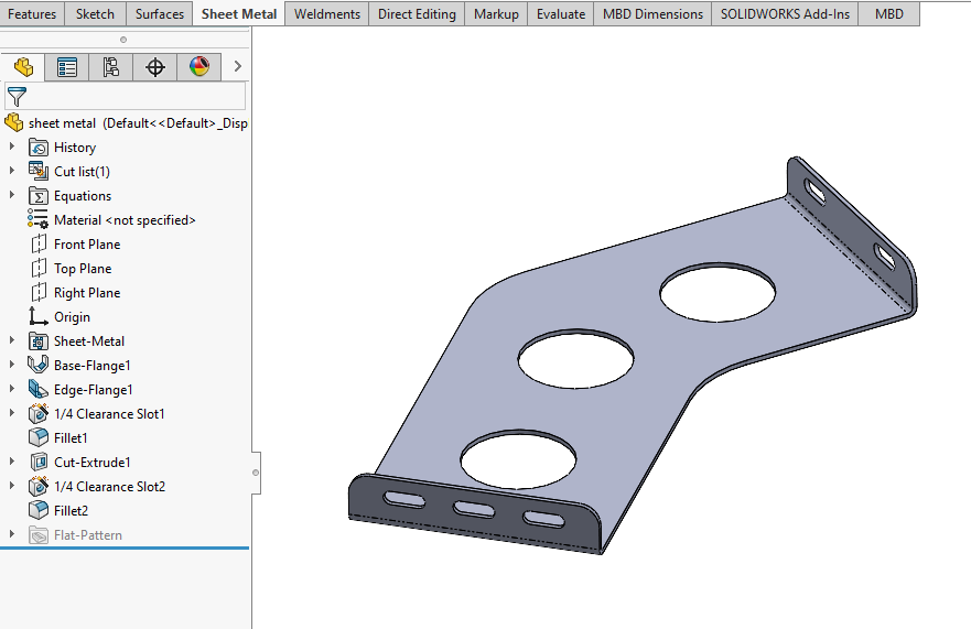
Method #3 – Export a Flat Pattern
Sheet metal parts include a unique feature called a flat pattern. It’s the shape of the material before any bends are made. It also includes the locations of all the bend lines. For parts you intend to use with SendCutSend’s bending service, this is the best way to export the DXF.
Step 1
Create a sheet metal part. Include all the bends and features you need.
Step 2
Right click on the “Flat-Pattern” feature and select “Export to DXF/DWG”
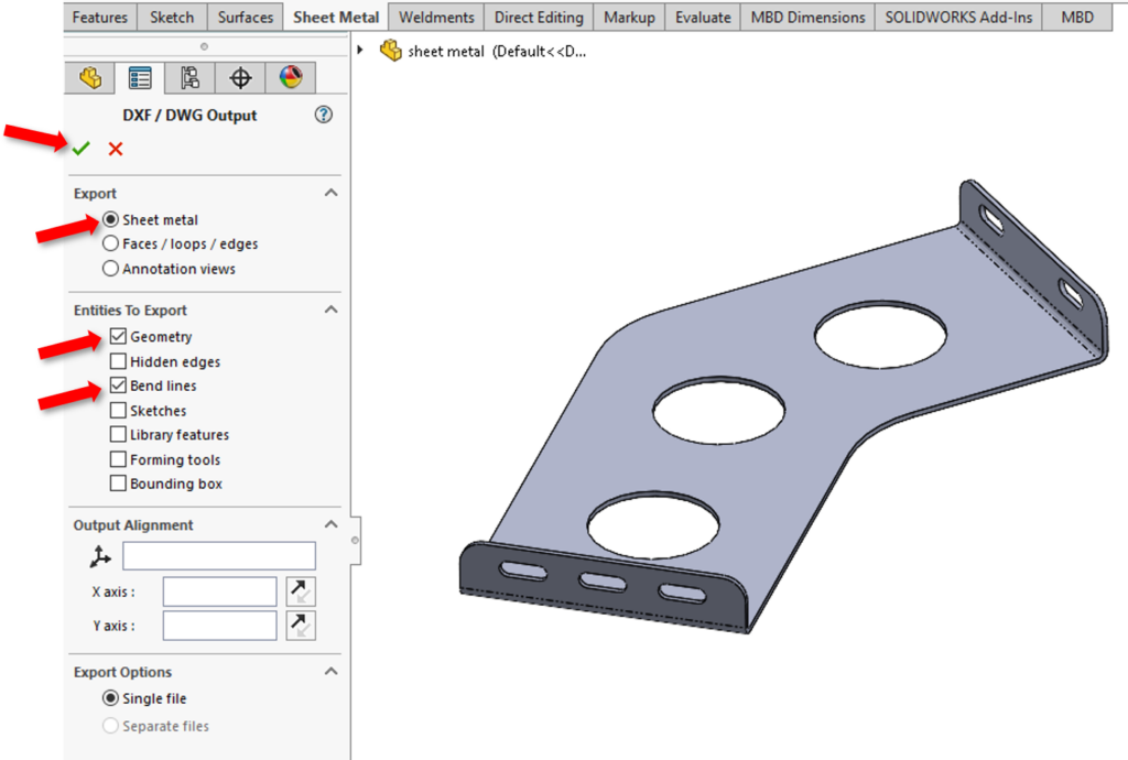
Step 3
This will bring up the DXF/DWG Output window, very similar to the one when exporting any flat face. However, this one will have the “Sheet Metal” option to export. Be sure that button is selected, and choose the entities you want to export. We’d suggest selecting “Geometry” and “Bend Lines”, and unchecking everything else. Bend lines are optional, but if you want to use SendCutSend to do the bending, include them in your DXF. Once you’re made all your selections, click the “Green Check Mark”.
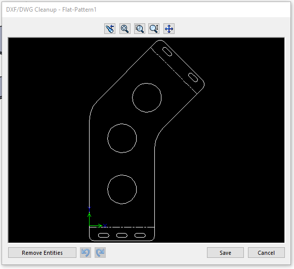
Step 4
Just like the other methods, this will bring up the DXF/DWG Cleanup window. You should see the flat pattern of your part with bend lines as dashed lines. You can remove any unwanted lines here by selecting them and clicking the “Remove Entities” button. If everything looks good, select “Save” and your DXF will be created.
Other Methods
You can export a DXF of an entire part or assembly simply by using the “Save As” command and changing the file type to DXF. We don’t recommend this method to produce DXFs for cutting as it pulls in all the geometry. Just know that it is possible if you need to create a DXF for other purposes.
Prepare Your DXF Files and Get a Quote Today
We want to help get your files in the best shape possible so you can utilize all the services SendCutSend has to offer. Exporting to DXF from SolidWorks with these steps should give you exactly what we need without any extra lines. If you have any other issues with your files, here is a list of things to check first. If you’re interested in more Solidworks tutorials, we’ve compiled a list here.
- How to Design Tab and Slots Using Solidworks
- Best Free CAD Software for Beginners & Advanced Users
- How to Create Text in Solidworks
- CAD tutorials
When you’ve got your design ready, upload the file to our website for instant pricing, pick your material and quantity, and your parts will be on their way!
