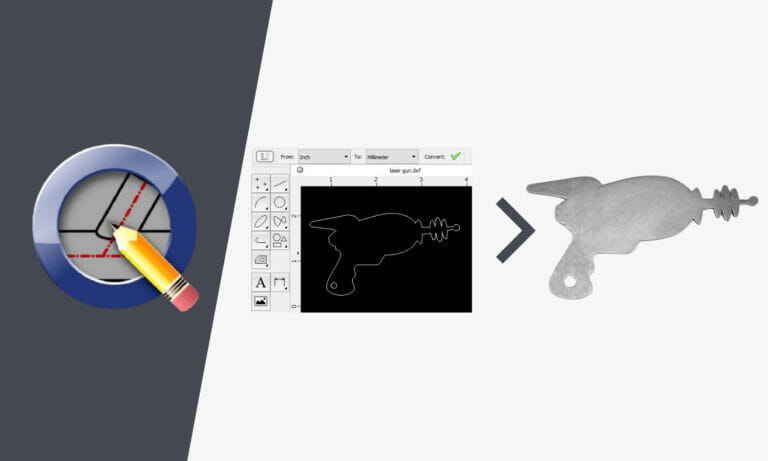
Whether you’re a CAD pro or new to any kind of software, QCAD is a simple, no-cost tool to help get your design ready for laser cutting. It’s an open-source 2D design program, with a simple interface, wide range of tools, and thorough documentation. These features help make QCAD one of our most recommended software.
Since QCAD is set up for 2D design, it can be perfect for drawing parts that don’t need the horsepower of a 3D application. And for projects that require 3D modeling in software like Fusion or SolidWorks before a 2D cut file can be exported, QCAD is helpful for making sure your exported DXF file is ready for cutting. You can check the file for errors and confirm it meets our design guidelines before you place an order.
Common issues QCAD can help find and resolve include:
- Geometry too small to cut in desired material
- Parts at the wrong scaling (not 1:1)
- File exported in wrong units (not inches or millimeters)
- Part is shown in a perspective view rather than flat
- Cut features on bent parts may be distorted
- Flanges too short to bend in desired material
- Duplicate paths and/or zero-length entities
- Intersecting paths, stray unintentional lines
- Excess nodes/anchor points
Getting Set Up
You can download QCAD’s free Community Edition bundled with a free trial of their Professional features here: QCAD – Download
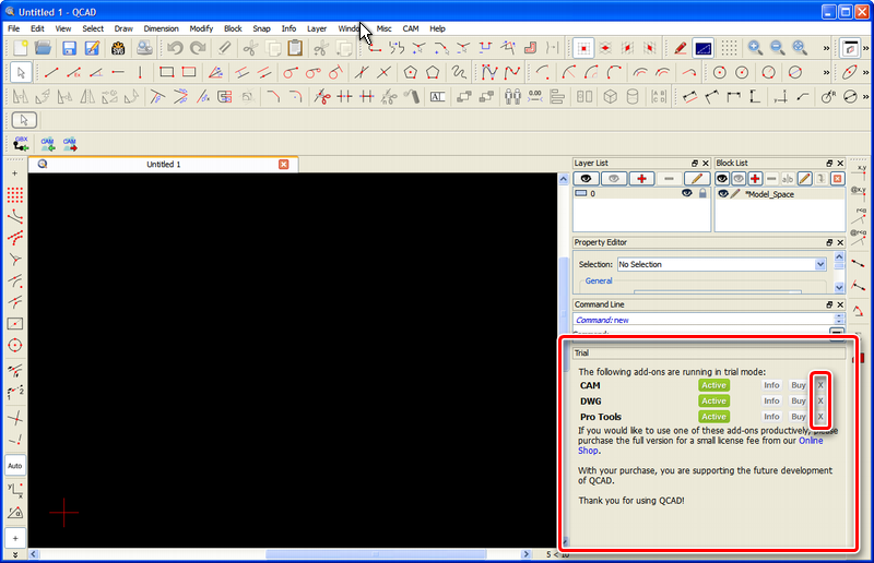
Once you’ve installed and opened QCAD, the QCAD Professional trial will run for 15 minutes at a time, at which time the program can be restarted and the Professional trial will run for another 15 minutes. You will not lose your progress when you restart as long as you have saved it consistently. If you would like to stop the QCAD Professional add-on from running in trial mode, you can do this by clicking Remove in the Trial widget and following the on screen instructions.
You can find more detail in this post in the QCAD forum.
Although QCAD’s free Community Edition includes a host of useful features, some of the most time-saving tools like duplicate path and zero-length entity detection require a QCAD Professional license, which is available to purchase. You can see the complete list of free versus Pro features here.
The complete manual can be found here: QCAD User Reference Manual
Step 1: Workspace Setup
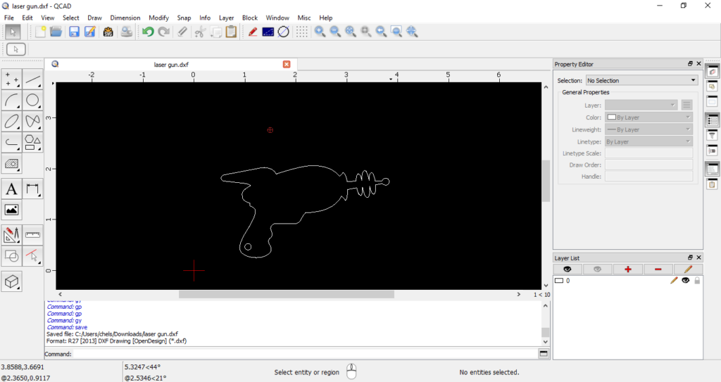
When you open a file in QCAD, this will be the general view:
The main windows you’ll want to have open are the “Property Editor” (GP) and the “Layer List” (GY).
Your toolbars will always be visible, but you may need to press the quick keys or navigate to View > Layer List and View > Property Editor to open the most frequently used windows.
Step 2: Using the Property Editor
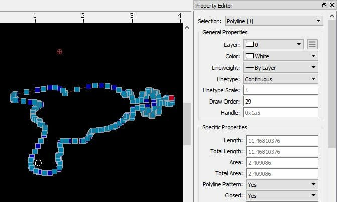
The Property Editor displays all information about a selected entity or group of entities, and allows you to change many properties. For example, this is where you can move entities from one layer to another.
You can select any entity using the cursor (QQ) tool:
- Layer: We recommend keeping all geometry on layer 0 and deleting any other layers.
- Color: All geometry should be the same color unless otherwise specified for bending setup
- Linetype: We require Continuous linetypes for cut geometry, and Dashed for bend location paths.
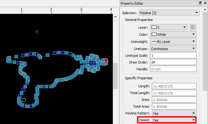
The Property Editor will also tell you if there are open contours. If the Property Editor says “Closed: Yes”, then the shape is fully closed. If the Property Editor says “Closed: No,” then the shape has an open contour that needs to be closed.
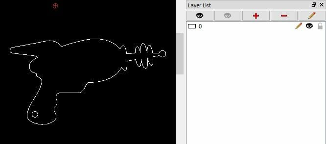
Step 3: Editing the Layer List
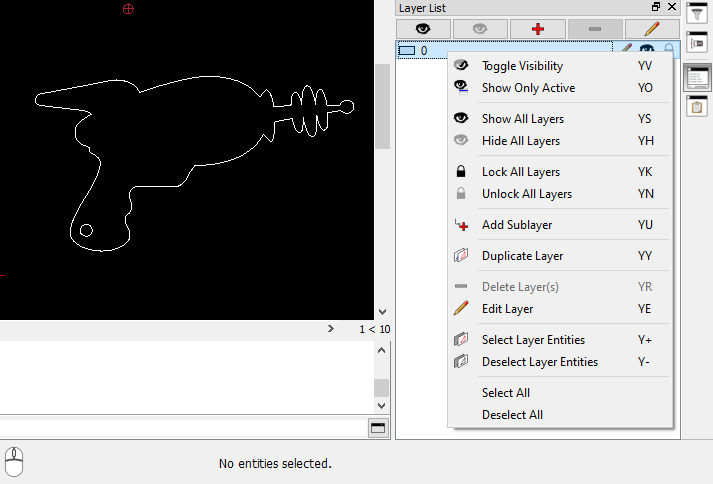
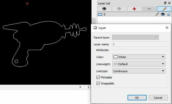
You can hover over any layer and right-click to make changes. You can also select a layer and press YE to edit the layer.
Step 4: Customizing Drawing Preferences
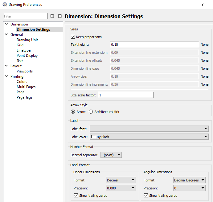
You can bring up the drawing preferences with the “Ctrl + I” keyboard shortcut. How you customize your drawing preferences is up to you, but there are a few dimension settings that we recommend using:
- Tick ‘keep proportions’ box
- Arrow style: Arrow
- Format: Decimal
- 3 decimal places for linear dimensions
- Tick ‘show trailing zeros’ boxes
Step 5: Customizing Application Preferences
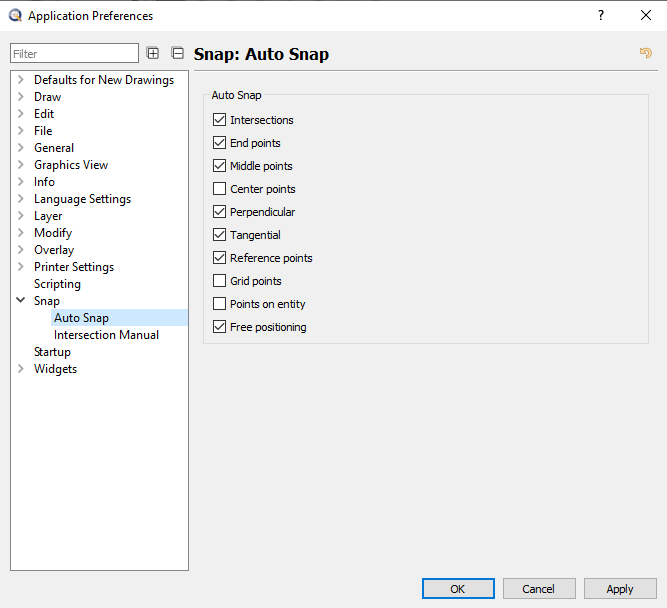
Auto Snap for Dimensions
The settings shown below in Edit > Application Preferences > Snap > Auto Snap may help with getting measurements where you want them. Un-checking “Grid points” is recommended, but auto locking for middle points and/or center points of any entity is very useful.
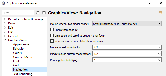
Mouse Behavior
If you’d like to change how your mouse interacts with QCAD, you can go to Graphics View: Navigation.
Common Commands
One of the biggest learning curves for any CAD program is the keyboard shortcuts and commands. These change from software to software, but utilizing them in your own work can help speed up your design process by a significant margin.
QCAD has a cheat sheet of quick keys but we’ve written out a few of the most common ones:
- GR: Graph on/off
- DF: Draft Mode – make all paths minimum line weight, similar to Outline mode in Adobe Illustrator.
- TA: Select All geometry
- CU: Convert Units
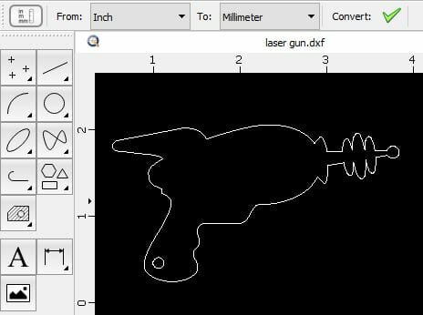
Sometimes QCAD is not correct about whether the source unit is MM or inches, or it shows no source unit. In that case, you can use the aligned dimension tool (DA) to confirm if the overall size of your part is measuring correctly.
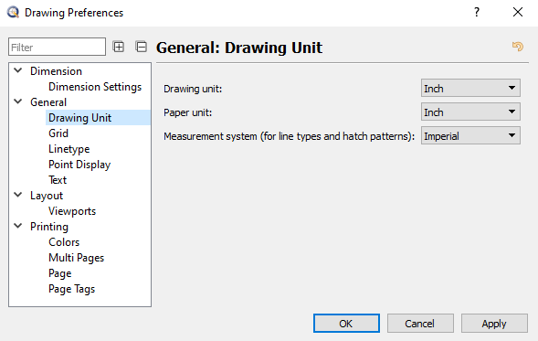
If the measurement is correct but you need to update your drawing’s units, open the Drawing Preferences (Ctrl + I), navigate to General > Drawing Unit, select your desired unit (mm or inches) and click OK.
- QQ: Cursor to directly select anything or “reset” your tool selection. Use this to manually select and delete stray paths or other unwanted entities.
- OC: Creates polylines for all entities selected
- + : Zoom In
- – : Zoom Out
Dimensions
QCAD’s measurement tools make it easy to measure twice and upload your file to our website once. You can double check the Design Considerations on the material info pages to confirm that your designs’ negative and positive geometry is no smaller than the minimum we can cut.
- DD: Diametric Dimension, only measures true circles
- DR: Radial Dimension, this only reads true arcs
- DA: Aligned Dimension between two points
- DH: Horizontal Dimension between two points
- DV: Vertical Dimension between two points
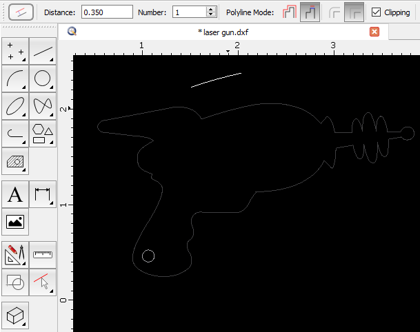
- OF: Offset with Distance.
Offset with Distance is a Modification Tool that is useful for showing dimensions. The tool will create a polyline or line segment that is offset the distance entered in the field.
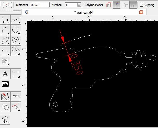
Here, the value of 0.350 is entered into the Distance field. Then you can move your cursor over your design’s geometry and the tool will show a polyline that is offset that distance. If you click the cursor, the polyline will be set in that location.
The Offset with Distance tool can be used to show the full die width of our tooling. You can find the die width for each bendable material on our material info pages under Design Considerations, and there’s a section on die line considerations at our bending guidelines page with examples of cut feature distortion.
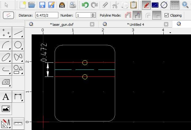
In the example below, the full die width for the material is 0.472”. The distance input into the offset tool is 0.472 / 2. Then the offset tool is used to bounce a demarcation line off of the dashed bend location line. Bend location lines should always indicate the center of each bend. We can see that the cut features highlighted in yellow will be distorted when the part is bent.
We do not have cosmetic protection within our die line for bending, so cut features along and within there can be affected and warp. You will need to keep all cut features outside of the full die width to avoid distortion.
You can use the Offset tool to check if your cut features will be distorted. If you do not object to distortion, you can leave an order note confirming this, which will help your order proceed to production smoothly.
Angles
DN: Angular Dimension
This is useful for checking if bend lines are parallel to an edge. We need all bend lines to have a parallel edge for our tooling to gauge against so that the operation can be completed successfully.
When you are using the Angular Dimension (DN) tool and measuring two parallel paths, the tool usually does not display a measurement like 0 degrees. If the tool displays no measurement, it means the paths are parallel. You can double check that the tool is working correctly by measuring two paths that are not parallel and confirming that it is measuring as it should be.
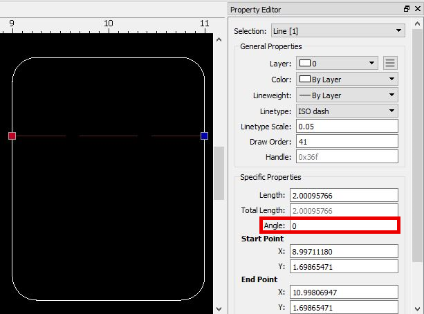
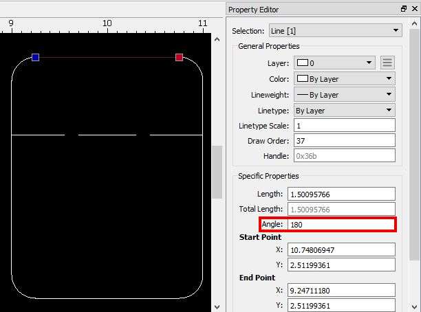
You can also use the cursor (QQ) to select the path you want to confirm is parallel to another, and check the angle of the path in the Property Editor (GP.) Then deselect the path and select the other path to check its angle. If the other path is the same angle or the same +/- 180 degrees, you’ll know it is parallel.
Nodes
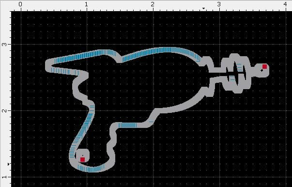
TA: Select All
You can use this tool to see all nodes/anchor points in your design. Each node/end point/anchor point represents a stopping point for the laser, CNC router, or waterjet during the cutting process. Therefore, designs should ideally have no more anchor points than needed to cut the design.
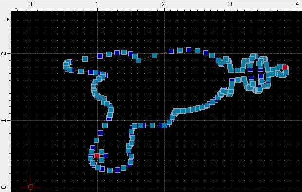
This is typical node density for a design of this complexity and size:
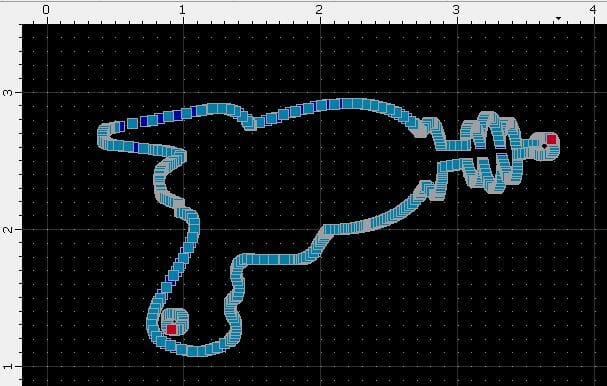
This is above average node density for a design of this complexity and size, and would compromise cut quality. We recommend exporting a cleaner file from the native design program with simplified paths and fewer nodes.
This is abnormal node density for any design, and would result in poor cut quality. We will automatically reject and send back files that contain too many nodes like this one because they cannot be processed correctly for cutting.
QCAD has simplification tools for spline and polyline entities to help with high node counts, but they may not fix all the issues in your design:
- OS: Simplify Polyline
- NP: Simplify Spline
While a clean vector file exported from your native design program is ideal, if a simplified export is not possible, you may want to try redrawing the circles and arcs in your design in QCAD and deleting node-heavy areas once the new geometry is traced over it.
Stray Points
Sometimes stray points will make their way into a design, and they’re easy to delete.
First, select all geometry with the TA command.
Then look at the Property Editor (GP) where you’ll be able to see all entities and their types at the drop-down menu at the top.
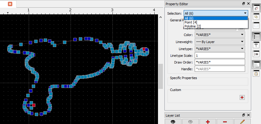
Select the Points and move them onto a sacrificial layer.
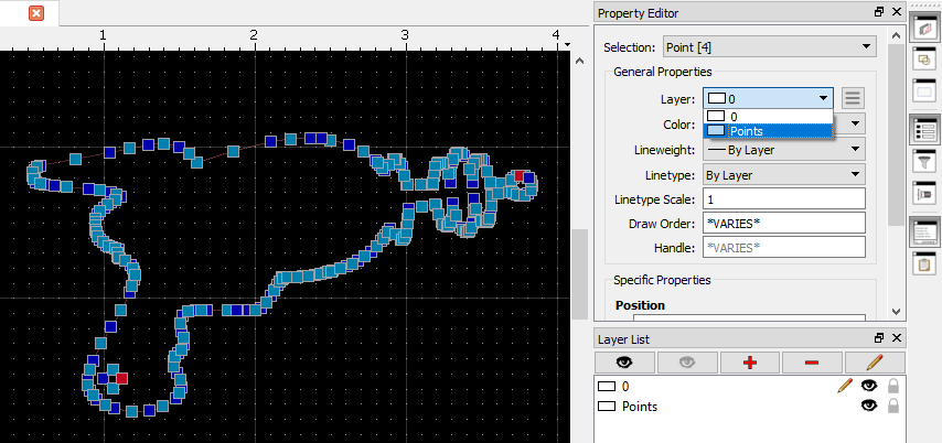
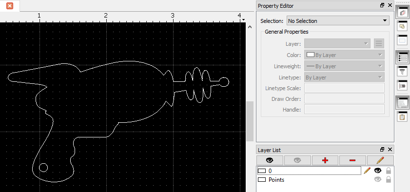
If you hide the layer, the points are hidden. Delete the layer.
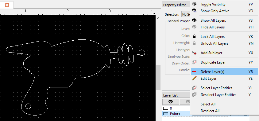
Your drawing is now free of random stray points!
Duplicate Entities
XP: Explode
This command converts selected block references, polylines, splines, ellipses, texts, dimensions and hatches into more basic entities. You may need to use the Explode (XP) command multiple times in order to detect all duplicates and zero length entities, and even then the tools may not catch them all.
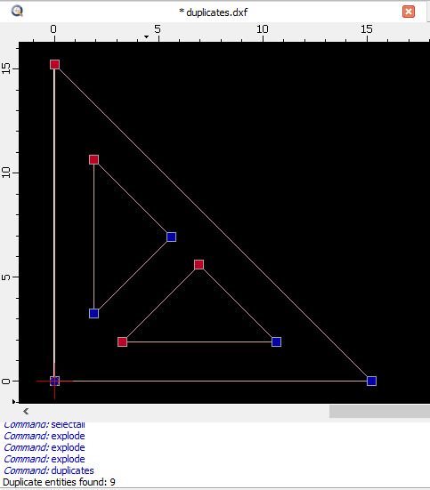
MD: Detect Duplicates (for selected entities, detects duplicates)
MZ: Detect zero length entities (press TA to select all entities in drawing first, then press MZ)
You can see the results of the detection tools in the Command Line (GM).
Removing Duplicate Paths
Duplicate paths are often the result of a surface being projected more than once during the file export process. If a design has many duplicate paths or zero-length entities that can’t be easily removed, it’s worthwhile to try and export a cleaner file.
The QCAD duplicate detection tool is not perfect and doesn’t always find all duplicates.
You can see duplicate paths by uploading the file to the instant pricing tool and clicking the preview image. The preview will show a thickened line where duplicate paths exist.
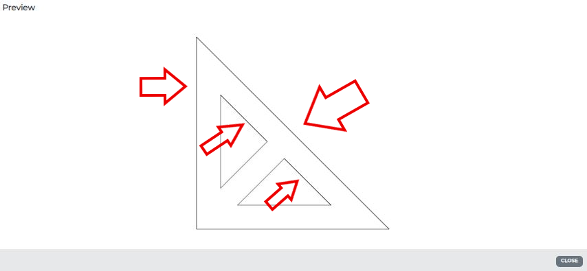
If a better file can’t be exported, it will be necessary to manually select the duplicate paths using the cursor (QQ) and delete them.
Blocks
Blocks are essentially locked groups of paths within a drawing that need to be specifically opened to be changed. This is done through the Edit Block (BE) or Edit Block-in-place command in QCAD.
Blocks tend to hinder most commands. You can easily get rid of blocks by selecting them and hitting XP, and then all geometry in the block will be released and you can proceed to preflight your file. Sometimes you will need to explode block areas multiple times to unlock any groups within groups.
After exploding blocks, you will need to use the Purge Unused Blocks command (BP) to avoid trouble uploading your file later.
Recap
Now that you’ve had a crash course in QCAD, you’re ready to preflight your files and fix any errors you might find before ordering! Once you’ve completed the preflight checklist, upload your file to our website for instant quoting.
Preflight Checklist:
- File is a two-dimensional vector format file
- QCAD is optimized for DXFs (free version) and can open more formats in QCAD Pro
- Is your design truly a flat, top-down representation of the part?
- If your design is shown in a perspective view, it needs to be exported again so that only the flat 2D face of the part is showing. We have export tips here.
- If your design is shown in a perspective view, it needs to be exported again so that only the flat 2D face of the part is showing. We have export tips here.
- All holes/negative geometry and bridging/positive geometry meet the minimums for the chosen materials and thicknesses, please reference the individual material info pages
- Use DA and DD tools to measure linear and diametric dimensions
- Use DA and DD tools to measure linear and diametric dimensions
- CNC and waterjet cut parts have minimum hole widths according to the guidelines
- Minimum 0.125” holes for CNC cut parts
- Minimum 0.070” holes for waterjet cut parts
- File is built at a 1:1 scale, preferably in inch units
- Use Convert Unit (CU) to convert units of measurement if needed
- Use Aligned Dimension (DA) to check overall part size is correct
- All objects are on the same layer
- Use Property Editor (GP) to move all geometry onto layer 0
- Use Layer List (GY) to delete any superfluous layers
- All stray points, duplicate lines, empty objects and text areas have been removed
- Stray Points
- Use the TA command to select all geometry and check if there are stray points.
- If there are, move them to a sacrificial layer and delete the layer.
- Use the TA command to select all geometry and check if there are stray points.
- Duplicate Paths and Zero Length Entities
- Use the TA command to select all geometry
- Then use the XP command to explode all geometry 2-3 times
- Use the duplicate detection (MD) and zero entity detection (MZ) tools to find and delete any duplicates and zero length entities.
- Empty Objects
- Use the Purge Unused Blocks command (BP) to remove empty objects
- Text Areas
- Delete text that is not needed.
- If you’re using QCAD Pro, you can use XP to explode text objects into paths for cutting.
- Stray Points
- No shapes have open contours
- Use the cursor (QQ) or Select All (TA) to select shapes and confirm in the Property Editor (GP) if the contours are closed.
- Use the cursor (QQ) or Select All (TA) to select shapes and confirm in the Property Editor (GP) if the contours are closed.
- All shapes have been united, combined or merged
- Use OC to unite shapes into polylines if needed
- Use OC to unite shapes into polylines if needed
- For bent parts, flanges meet the minimum length for bending in the material per the individual material info pages
- Use the DA command to check flange length
- Please note: we need the minimum flange length to be met on both sides of the bend to avoid inaccuracy or part failure during the operation
- For bent parts, cut features that fall within the die line of our tooling will be affected and warp.
- Use the OF command to see if cut features in your design will distort.
- Use the OF command to see if cut features in your design will distort.
- All text has been converted to outlines or paths
- If you’re using QCAD Pro, you can use XP to explode text objects into paths for cutting.
- If you’re using QCAD Pro, you can use XP to explode text objects into paths for cutting.
- Cut-out text (reversed text) has bridges or has been stencilized
- We have tips on preparing text for laser cutting services here.
- If you aren’t worried about losing interior shapes, delete them from your design.
