The term “small geometry” in laser cutting is used to describe designs and design features that are very intricate and/or small. Usually this can include things like holes, slots, “bridging” features, or sharp edges in small shapes. This is extremely common and often seen in parts for jewelry, robotics, and computer hardware.
What is small geometry in laser cutting?
Small geometry in laser cutting refers to design features that are small and created by the cutting process. If geometry is too small, it can cause problems in productions. Although lasers are extremely precise and can cut through many different materials, there are still limits to how small features and parts can be. At small scales, the manufacturing process becomes more difficult as the cut method loses resolution. For example, in the case of parts with features smaller than the kerf width, material that is burned away by the laser can be lost. That’s why it’s beneficial to understand kerf in laser cutting if you’re designing a part with small geometry.
In some cases, even post processes can damage small geometries. For example, if parts require ceramic tumbling, tumbling forces can wear down delicate features.
Small geometry limitations depend on a variety of factors; material type, material gauge, cut method (fiber laser, CO2 laser, CNC router, waterjet), and post process options like tapping and deburring.
Fortunately we provide guidelines for each of our services to give you peace of mind that your small geometry can be cut. We also have some best practices for designing and laser cutting small parts.
How does small geometry impact our lasers?
We have multiple cut methods (fiber laser, CO2 laser, CNC router, waterjet) and they’re all impacted differently by small geometry. There are guidelines for each of these cut methods:
Some design requirements relating to small geometry and lasers (lasers are often used for metals, natural materials, composites, and some plastics):
- Refer to SendCutSend’s part size limitations chart to confirm the minimum overall part size for the material you need.
- For laser cut parts, holes, slots, and cutouts need to be approximately 50% of the material thickness. This is because the laser “pierces” the material to begin cutting, which requires a certain diameter allowance for holes and other internal shapes.
- Keep geometry no smaller than the minimum hole size for the material thickness, which can be found on the individual material info pages
- Ensure all ‘positive’ geometry or bridging meets our minimum bridging size for the material you need. These specifications can also be found at our materials directory
- Files should be exact size to be cut (1:1 scale)
- Required units are inches or millimeters
- Fonts should be stenciled or connected with “bridges” to prevent features from falling through and being lost
- Be sure that no lines overlap or intersect with each other and that there are no open contours
Some design requirements relating to small geometry and the CNC Router (CNC router is usually used for composites, wood, and plastic):
- Minimum part size is typically 1” x 2”; be sure to confirm this for your chosen material
- Minimum hole size for CNC routed materials is 0.125” due to the size of the cutting tool.
- Ensure all ‘positive’ geometry or bridging meets our minimum bridging size for the material you need. These specifications can be found on each material info page.
- Plan for inside angles to be radiused due to the use of a round cutting tool. The radius will be .063”, and this will be more or less pronounced depending on the size and angle of any interior corners.
- For designs like grilles with a significant number of perforations, we recommend no more than 50% material to be removed to avoid risk of the part moving during the cutting process.
Some design requirements relating to small geometry and the Waterjet (Waterjet is usually used for thicker metals, natural materials, composites, rubbers, plastics):
- Minimum part size is typically 1” x 2”; be sure to confirm this for your chosen material
- The minimum hole size for waterjet cut parts will be 0.070” or 0.125” depending on the material and thickness. These specifications can be found on each material info page.
- Ensure all ‘positive’ geometry or bridging meets our minimum bridging size for the material you need. These specifications can also be found at our materials directory.
- All internal corners will have a radius of .032”.
- Files should be exact size to be cut (1:1 scale)
- Required units are inches or millimeters
- Fonts should be stenciled or connected with “bridges” to prevent features from falling through and being lost. Make sure any bridging meets the minimum bridge size for the material. These specifications can be found on each material info page.
- Be sure that no lines overlap or intersect with each other and that there are no open contours
These are just a few of the design requirements for each cutting machine. By no means is it an exhaustive summary of the machine guidelines, so we strongly recommend referencing the cutting machine guidelines at the links provided and thoroughly reviewing the information.
Small geometry and materials
As mentioned before, the type of material can also be a limitation for small geometry and should be taken into consideration alongside cut method limitations. Fortunately, for each of the materials we offer there are guidelines and details on the material page that can be referenced. Below you can find material details for a few popular materials:
The material details include critical minimum specifications by stock thickness such as cut tolerance, minimum hole size, minimum bridge size, tab/slot tolerances, minimum flange length, smallest tap, and minimum size requirements for finishing services. Reviewing material-specific details is highly recommended before finalizing and submitting your part. Blue tempered steel, aluminum, and stainless steel are some of the best options for designs requiring small geometry.
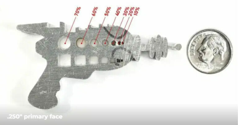
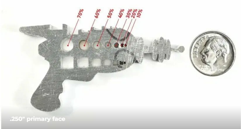
To gain visual insight into small geometry defects, check out the figure below taken from the 5052 H32 aluminum material details. It is a test part cut out of 0.250” thick 5052 aluminum. As shown, it’s evident that as the hole size goes below 50% of the material thickness, the quality and resolution of the features begin to suffer.
In addition to service-specific design guidelines, you can reference the material minimum and maximum size master list to quickly survey the available size ranges for all materials offered by thickness and quote type.
Additionally, the chart indicates the cut method used for each material and thickness. This is a good resource to consult early in the design process as it presents a comprehensive summary of size requirements.
Another helpful design resource is the processing min/max chart.
This page provides size requirements for bending, deburring, powder coating, and tapping for each material and thickness available for those services.
Tips and tricks for small geometry design
If you need to design parts with small geometry, we recommend taking advantage of guidance available in our blog for ideas and best practices.
Design Advice for Small Scale Applications
Best Practices for Designing and Laser Cutting Small Parts
While planning your design, ask yourself some questions:
- What is the intended material type and sheet thickness?
- Is the part flat or will it be bent?
- Does the part need deburring?
- Any countersinking or tapping?
- Does the part need finishing services?
- Try to keep the guidelines for all these processes and materials in mind.
Another way to approach the small geometry design process is by reviewing the general min/max part size requirements for materials and processes to help inform your material/thickness selection choice and gain an understanding of the type of cutting machine that will cut your part. Once you have an idea of the material and cut process, you can refine your understanding of the material-specific design requirements for small geometry by referencing the material details. Finally, you can refine your understanding of the cut method limitations by referencing the service guidelines.
Conclusion
Lasers, CNC routers, and waterjets are amazing machines, but they can’t do everything! We highly recommend reviewing the guidelines mentioned in this article when designing your next part. There are many considerations, but they’re easy to follow once you have material, thickness, and post-processing requirements in mind. Practice this upfront due diligence and avoid designing a tiny hole in a thick piece of steel that later melts under the laser or designing a piece of lace that is too fragile and breaks during tumbling.
Of course, you can always reach out to our support team with any questions you might have, or check out our FAQ page! We’re more than happy to help you confidently bring your small geometry designs to life.


