In this tutorial we’ll cover all the basics for designing your files with bends.
Before You Begin
We realize everyone has a different level of knowledge and experience. We’re here to help you at every stage of the process. If you’ve never sent us a file before, or are unfamiliar with designing for metal bending, we have a few guides you may want to check out before proceeding:
SendCutSend Design Guidelines
Forming and Bending Guidelines
File Format

We accept either 2D vector files (.dxf, .dwg, .eps, or .ai format) or 3D files (.step or .stp format). If you upload a .step/.stp format file, see our 3D File Guidelines.
Keep in mind that the bend radius and K factor is set for each material thickness, and we do not offer custom bend radii at this time. We strongly recommend using our Bending Calculator and referencing our bending specifications to ensure your parts turn out as expected.
- Using Autodesk Fusion or SolidWorks? Download our gauge tables to apply our latest specifications with a few clicks.
You will be able to view your bends in a 3D model during the checkout process to make sure the angles and flange orientations are correct.
If you design your parts in non-CAD software (Adobe Illustrator), please send us the original (native) ai file. We’ll take care of the conversion on our end. While we accept .AI and .EPS files, it’s critical that your bend lines are parallel when uploaded from these software or the file will delay our process.
For the fastest turnaround on your order, we recommend designing your parts in a CAD software, such as Autodesk Fusion, AutoCAD, or SolidWorks.
There are two main things to note when designing for bending: bend locations and bend deductions. We’ll cover both of these points and more.
Bend Locations
First you need to decide where your bend (or bends) will be on your part. Some things to keep in mind are the minimum flange length and maximum bend length. The minimum flange length and maximum bend lengths can be found for all bendable materials here: Post Processing Specifications Chart
2D Format Files
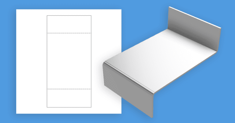
Once you’ve planned your bends, you will need to add lines to indicate where on your part you want the bend(s) to occur if you’ll be uploading a 2D file. We refer to these as the bend lines. You will indicate these lines differently depending on what file you are using. The following table explains exactly what indication we need from your software:
| SOFTWARE | 2D FORMAT | BEND LINE |
| Fusion | .dxf | Solid line (default) |
| Adobe Illustrator | .ai | Solid, separate color from cut lines |
| SolidWorks | .dxf | Dashed line (default) |
| AutoCAD | .dxf | Dashed line |
| CorelDraw | .eps | Solid, separate color from cut lines |
| Inkscape | .eps | Solid, separate color from cut lines |
3D Format Files
You can upload a 3D file in either the STEP or STP format.
These file formats are typically exported from 3D rendering software such as SolidWorks or Autodesk Fusion. If you’ll be sending us a STEP or STP file, be sure to follow our 3D File Guidelines.
It’s critical that your design is set up as a sheet metal part and uses our bend radius and K factor specifications for the material you’ll need. You can find all specifications for each material thickness on the individual material pages in our Material Catalog.
Learn more about material specifications.
Bend Deduction
When designing for metal bending, it’s important to consider bend deduction. Bend deduction is used to counteract material stretch caused by forming. This is unique to each material type, thickness, and bend angle. Don’t worry, we’ve created a calculator to help you make your measurements spot on.
Advanced-user note: all calculations should be for air bending – not coining.
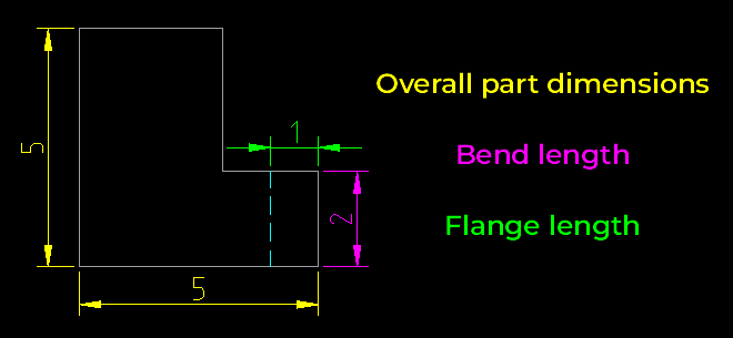
Once you have your new measurements from the bend calculator, you’ll want to adjust your design file accordingly. You will be reducing the length of your base and flange to accommodate the length of the bend itself. See the illustration below for an example. The green line indicates where the bends will occur. Keep cut out areas and holes away from these lines to avoid distortion.

Bend Radius
The bend radius and K factor is set for each material thickness we bend, and cannot be changed upon request. You can confirm bend radius and other specifications for each material thickness we bend in our handy bending specification chart.
If you’re designing in 2D, use our Bending Calculator to ensure your parts will turn out as expected. If you’re designing in a 3D program like Fusion or SolidWorks, set up sheet metal rules using our bending specifications.
Bend Angles
When designing and calling out your bend angles, it is important to note that the angles are measured on the outside of the bend. See the example below. The acute bend is measured as 130°, and the obtuse bend as 45°.

Exporting Your Design
We’ve set everything up on our end to make uploading as painless as possible. When designing in Illustrator, please send us your files in .ai format. Take a look at our export guides if needed.
As always, before you upload your file, use our checklist to make sure your file is ready to be cut.
Check out our processing page for information about typical lead times for parts with bending and other services. We provide free 1-3 day shipping for standard orders (higher quantities may require additional time). Most bent parts will ship ground as they will exceed 2″ in height when packed.
You’re Ready to Bend!
Now that you’ve had a crash course in designing for metal bending, you’re ready to upload your file and get an instant quote for custom bent parts. If you run into any trouble our Support team can help. Happy bending!
