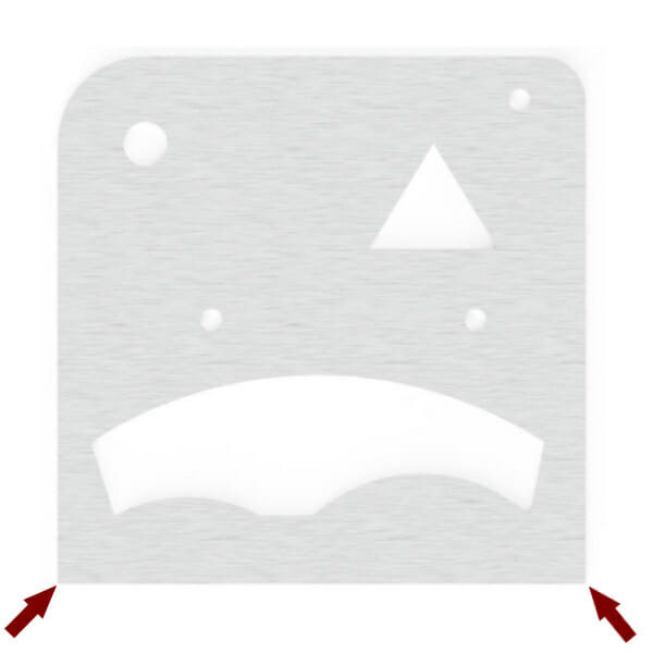
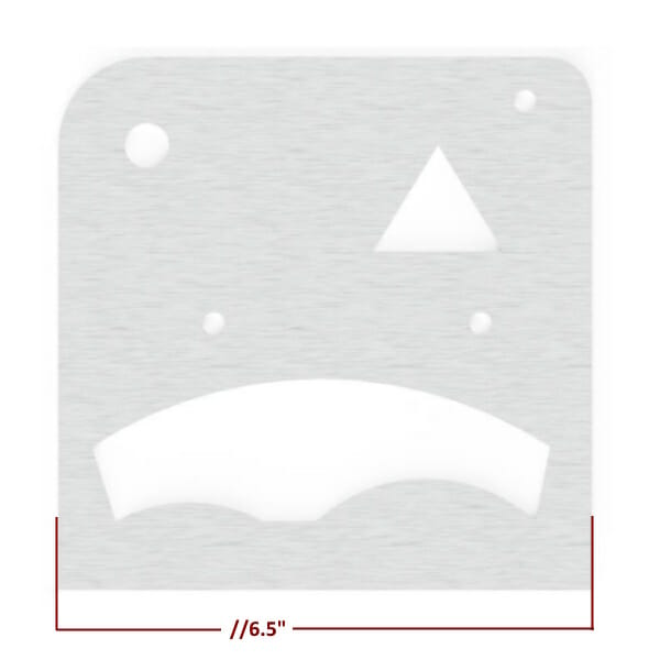
Typically, the best practice when measuring a part is to pick an area whose features are clear and easy to measure from. In the example part, either of the lower corners would work well. The upper corners would prove difficult to measure from because they are rounded.
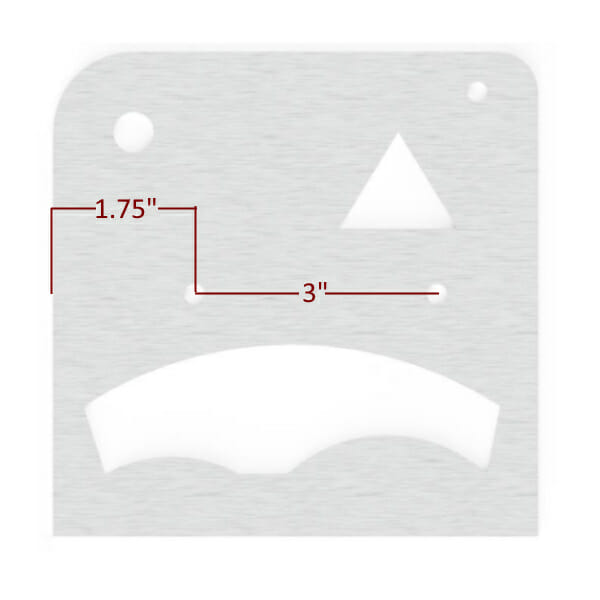
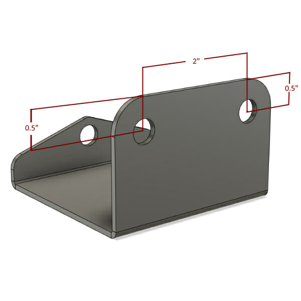
Before adding dimensions to your drawing(s), it is important to consider what the critical dimensions are and how to deal with stack tolerances between features. For instance, on the example part, the distance between the holes is more important to the design than where they fall in relation to the edge of the part. When that is the case, the part should be dimensioned as shown here.
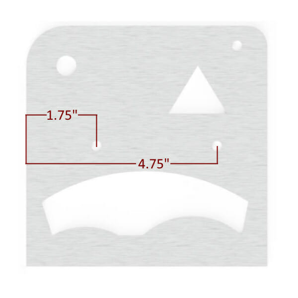
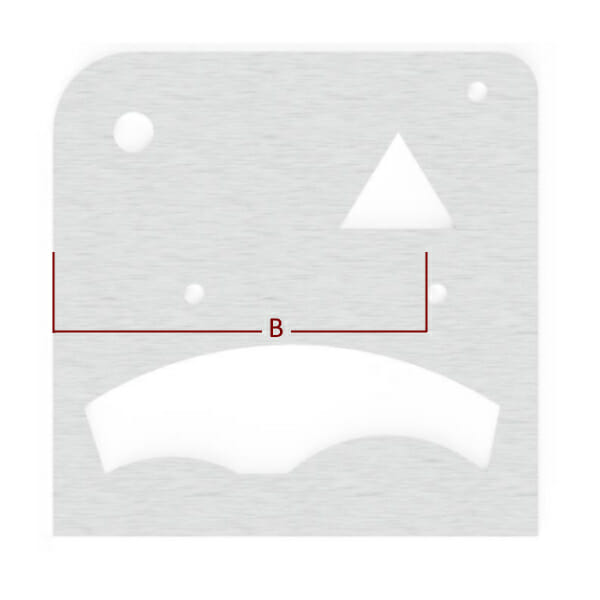
If the distance between the holes is less critical than their distance from the edge, the part should be dimensioned seen here.
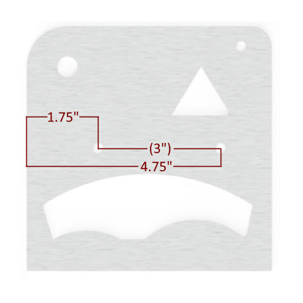
It is okay to provide redundant measurements, too. When providing redundant information, you should put the dimension in parentheses, as shown in the image. There is no such thing as having too much information, so long as it isn’t conflicting!
Once you start dimensioning a drawing, it can be difficult to stop. It is always preferable to err on the side of too many measurements rather than not enough. One of the base rules in GD&T (the practice of annotating technical drawings) is to avoid double annotation of any feature. If you’ve already defined the location and diameter of a hole, you do not need to include the radius as well. If the start and stop points of a line are defined, then the length of that line does not need to be defined.
When annotating a drawing, especially by hand, it is important to know when to stop for the sake of clarity. Even basic parts may need several drawings in order to avoid overcrowding with dimensions. We would prefer to work with several clear drawings rather than one or two that are hard to decipher. Adding redundant dimensions to a drawing is always OK, but please put non-critical dimensions in parentheses.
If you miss a dimension no worries! Design Services will reach out to you through email regarding any questions on your part.
Measuring a hole is an important part of both design and reverse engineering.
To accurately measure a hole, use the top/smaller end of your caliper and open the teeth against the inner walls of the circle. While being careful to keep the micrometer straight, rotate the part while looking for the largest number. That number will be the diameter of the hole.
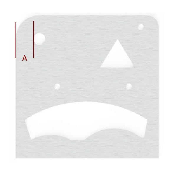
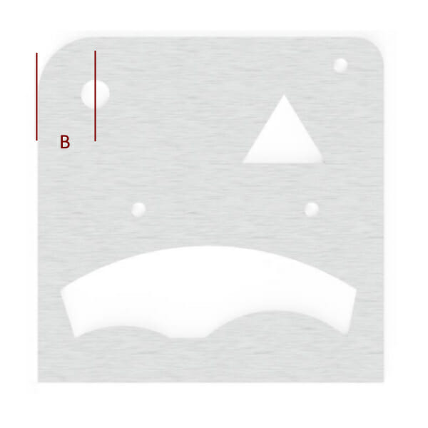
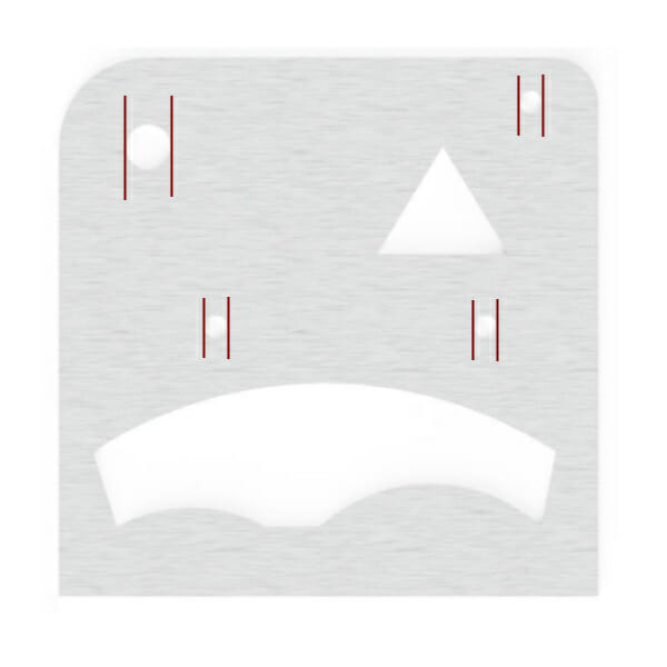
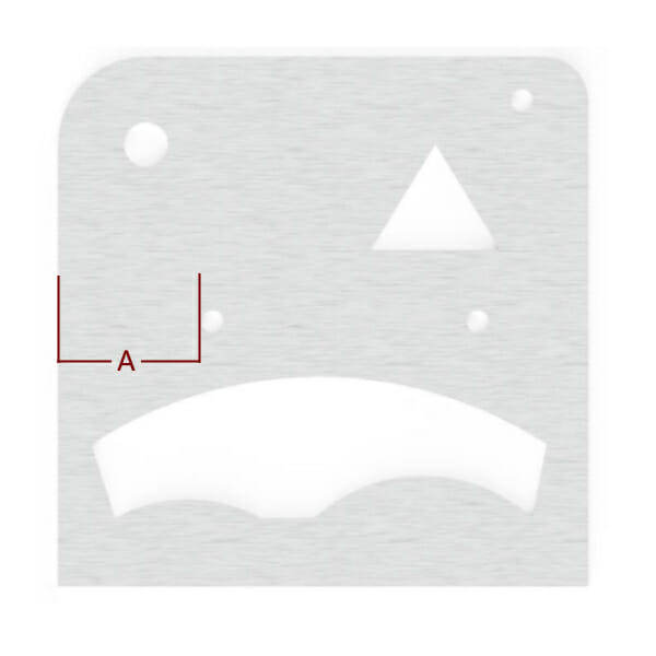
Measuring the location of a hole can be tricky, but careful checking and a little bit of math can make quick work of it.
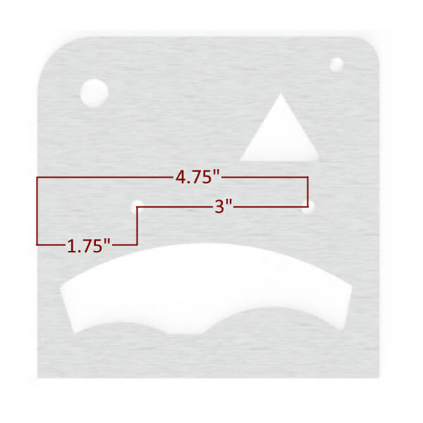
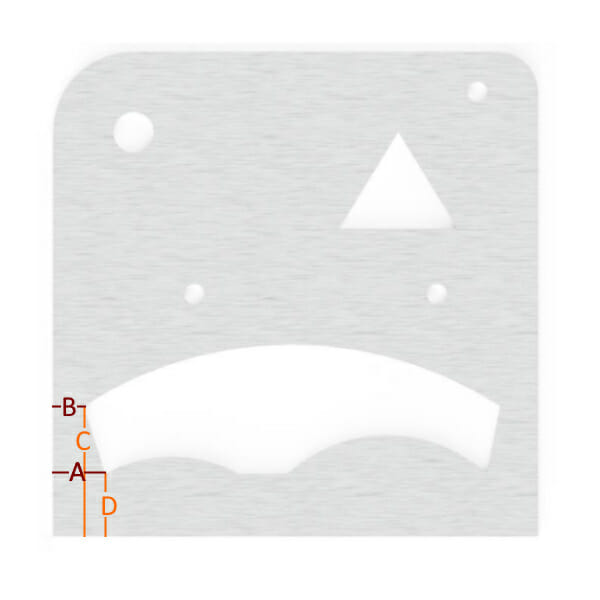
The first step would be to look at the edge of the part to the edge of the hole distance (A) followed by the distance from the center of the hole to the edge of the part (B). You can check your work by adding the radius of the circle (half of the diameter) to your findings for measurement (A), and it should be the same as measurement (B). The location of a hole should always be shown at the center point.
Measuring the distance between two holes is very similar to measuring a single hole. Whenever possible, measure both hole locations from the same side of the part. Never assume that the diameter of the holes is the same: you should measure each hole to ensure the design’s accuracy.
Use measurement A + the radius of the hole (half of the diameter) to determine the location of the first hole’s center point.
Use the measurement from B + the radius of the hole to determine the location of the second hole’s center point.
Subtracting the first hole’s center point measurement from the second hole’s center point measurement will provide the distance between the holes, no matter their diameter. The location of a hole should always be shown at the center point of the circle.
The measurement provided in scenarios like this is considered to be the critical dimension: If the center-to-center dimension is critical to your part, you will want to list that dimension while having the edge-to-center of hole dimensions shown in parentheses.

Measuring a square part is simple, but the measuring process may reveal that the part isn’t actually square. If your part isn’t square and it isn’t caught early on, it can affect dimensions all over your part! The easiest way to check this is to measure the part in several locations. If measurement #3 is consistently different than #1, your part has an angle somewhere!
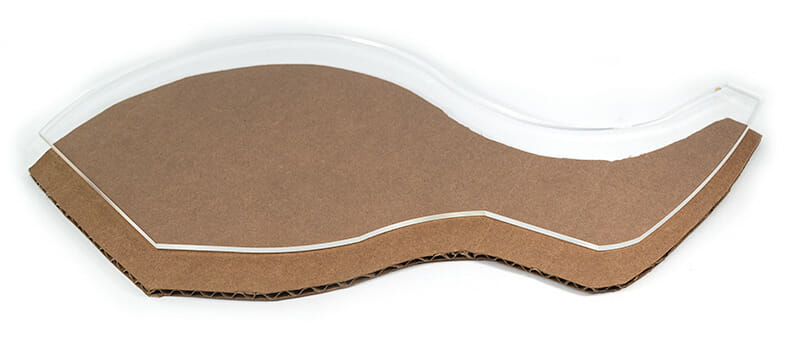
Measuring a complicated shape doesn’t need to be complicated, but it will require thorough measurements. In the example below, several measurements are required to communicate the location and shape of the feature properly.
Features like the one in the image can generally be broken down into segments and approached individually. If you consider each point on a design where a laser would stop or slow down and then change direction, that is where we will need another dimension in order to draw the design accurately. The segments of the feature can be approached as numbered on the image.
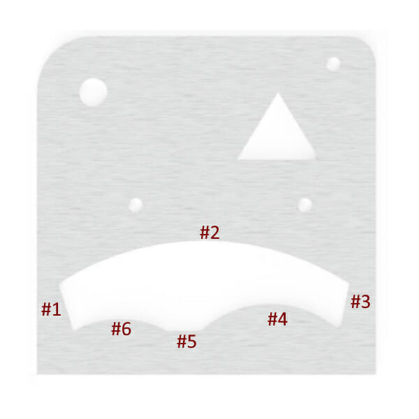
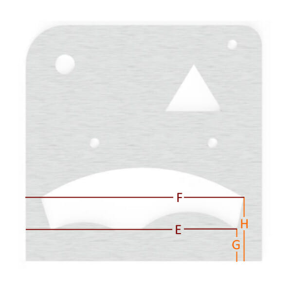
For areas #1, #3, and #5, we can simply locate two dimensions for the beginning and the end of the line. The dimensions in this instance, can be taken from the left side and the bottom of the design, as shown below. Only the point locations are required; knowing the angle of the line is not necessary.
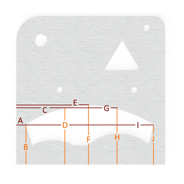
To define areas #2, #4, and #6, there are two ways of approaching the issue. If the geometry is known to be a true arc, defined by having a consistent radius, then only the start, stop, and highest/lowest point needs to be defined. If the geometry is not known to be a true arc, then we will need point locations along the shape so that we can connect the points into a continuous line. For a continuous line that changes directions, we will need a point for the start, stop, and highest/lowest points of each direction. For the image below, let’s assume that the arc is not known to be a true arc.
The points collected create a roadmap for the geometry to follow. In these scenarios, it is advisable to collect as many points as reasonably possible but also to be sure that the data is correct, too. Inaccurate dimensions can create a “bumpy” curve rather than a smooth one.
Measuring a rounded edge on an existing part can be a difficult task, but luckily, you’ll find that most designers use common numbers when designing. You are far more likely to find a .375” radius on a part than one that is .368”. Consider what part of the world the original part was designed in, too: While .236” isn’t a common number in SAE measurements, a 6 mm radius is not uncommon in other places because it is a whole, metric number.
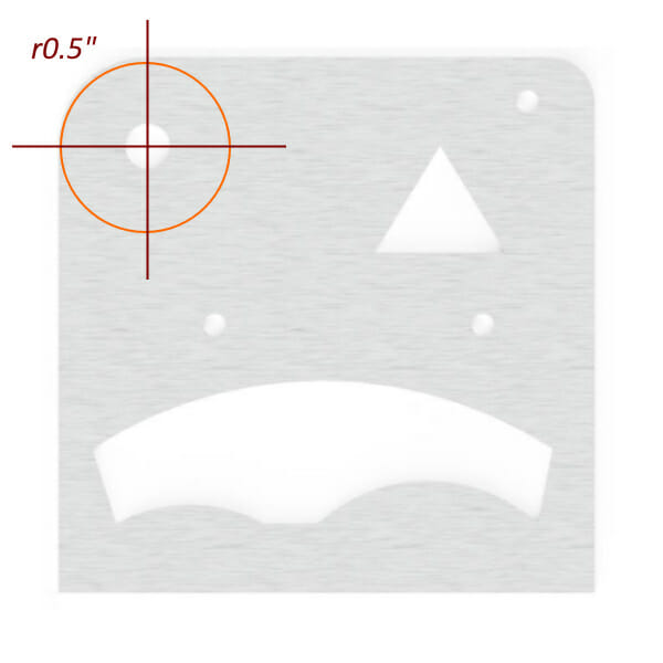
Measuring a radius on an existing part can be as simple as locating and measuring the point where arc starts to form away from a straight edge. The measurement that you take from one side of the corner should match the other side. If at all possible, mark the area (painter’s tape is good for this) and measure the intersection of the two points. This will give the radius of the corner, which can be indicated by using “r” before your number. In the image below, you can see the intersection points marked in red with the whole circle that the radius would be part of shown in orange.

Holes should be indicated by the ⌀ symbol. Design Services does not currently support 3D machined designs, so depth or “Thru” designations are not necessary.
When telling us about what additional services your part needs, it is important to remember that even though we are designing your part for you, we need to stick to the same list of available sizes and parts for each service.
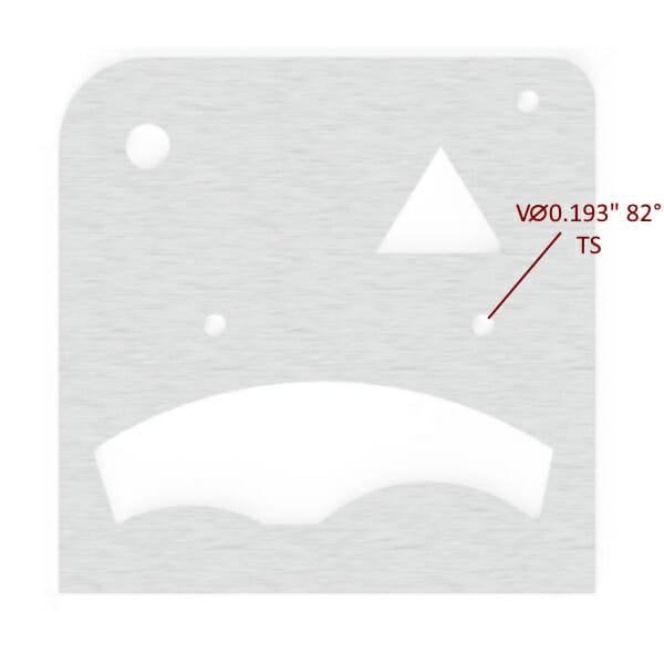
Countersinking is notated by the “Minor” (smaller) hole diameter only; the “major” (larger) hole diameter will be automatically set by our systems and is unnecessary to include. It is important to include either the letters “CSK” followed by the diameter and countersink angle, or the letter “V” followed by the minor diameter and the countersink angle. You will also need to tell us which side of the part you’d like us to countersink. This can be done by including the letters “TS” for this side, or “BS” for backside. You can find our list of available countersinks here. Please keep in mind that we cannot add multiple services to a single hole (we cannot tap and countersink the same hole)
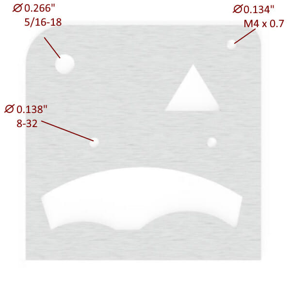
Tapping, just like standard holes, is only offered in 2D format. We tap through the entirety of the part only. You can find a list of materials and thicknesses that we tap, in addition to a list of thread sizes, here.
When indicating a tapped hole, you simply need to draw a line to the hole with text indicating the diameter and the tap size listed. There isn’t any need to add “thru” or depth to the annotations.
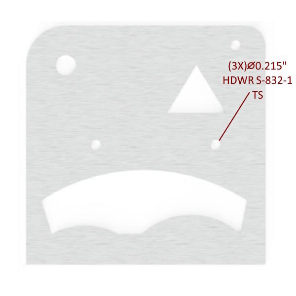
Typically, hardware is called out in a table on a technical drawing and shown on a 3D perspective view of the part. We don’t expect you to create a table for your drawings, but we do ask that you add three things:
The side that the hardware should be inserted from. This should be denoted by using “TS” for this side and “BS” for back side.
You can find the SKU and required hole diameter for each piece of hardware in our Hardware Catalog.
If you have several of the same size holes that will need the same hardware, you can begin your hardware callout with the number of like scenarios in this drawing. For example, you might have three holes in a part that all need the same hardware. You could save time and effort by calling out your hardware as shown below. If you only needed hardware inserted into two of the three like-size holes on this part, it would be advisable to note them individually to avoid confusion.
Bending on a part can be indicated in two different ways.
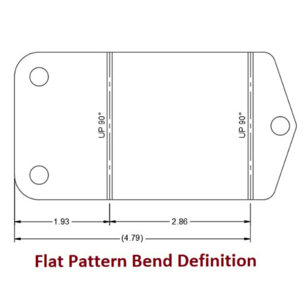
If you already know exactly where you need your bends to be on a flat part, then you can add them to a flat-pattern drawing of the part. Make sure that you indicate what angle and direction (up or down) the bend should go in.
If you don’t know the bend deductions, bend radius or K-factor for your bends, that’s OK! We’ve got you covered. What we’ll need is a side view of the part showing the desired outside dimensions of the flanges and the desired angles. Flanges are the part of your design that is going to be bent, whereas the stationary part is typically called the base. It is important to include outside dimensions for each flange on your part.
Please see the images below for the do’s and don’ts of bent part annotation.

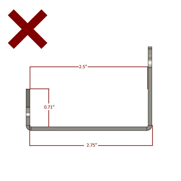
Some dimensioning considerations for bent parts will help the process go smoothly. It is best practice to dimension cut features from a fixed edge rather than from the inside of a bend. This is because the distance between the inside of a bend and a part’s edge will change depending on which materials and thicknesses are used for the part. If you dimension your features from a fixed point, they will be where you expect them to be despite material or thickness changes. Ideally, cut features for each flange would be dimensioned from their nearest fixed point parallel to the bend line.


The goal of annotation is to give the designer as much information as possible without the need for write it out with words. Parallelism and Perpendicularity symbols are two great methods of giving us the added information very quickly and easily. Typically, engineering drawings will have these two symbols followed by tolerance and datum specifications. Luckily, we’ve already defined our cut tolerance for each material on our Materials Pages. This means, all you need to supply is the symbols, and our lasers will take care of the rest.
You can use the parallelism symbol to tell us that to lines run perfectly parallel to each other. There is no need to make a new leader line for this symbol; you can add it as a prefix to your dimension. It is important to note that symbols for parallelism are not required, but they are helpful.
This symbol is used in a few different ways in traditional GD&T annotation, but luckily, we’ve simplified it for our uses here. The perpendicularity symbol is frequently used to define the allowable draft or runout on a given feature on a surface, but we’ve already locked that down for you, so for our purposes, we’ll use it only to define features that are perpendicular to each other in a two-dimensional environment. Just like with the parallelism symbol, this one isn’t required, but there is no such thing as too much information! To denote perpendicularity, just add a line pointing to the intersection of the two lines that form 90°. There is no need to annotate each 90° corner in your drawing; in the example below, the parallelism and single perpendicularity symbol constrain this shape to have four 90° corners.
We can typically create the file that you need in 1-2 business days. Oftentimes, we can create a file the same day if you provide clear sketches and instructions.
We’ll need dimensions for each feature on your design. This includes perimeter and internal features. See our guidelines above for more detailed information.
While pictures are extremely helpful, they leave a lot to be desired when it comes to accuracy. If you can supply dimensions in addition to drawings, we can definitely get your design completed for you.
Absolutely! There’s no need to be a graphic designer…you can use the stock Paint program on your computer to add dimensions to your photos.
No. We provide it for your convenience, but feel free to use whatever medium you’d like. If we can read it, we should be able to draw it for you.
Our Physical Reversal process uses state-of-the-art technology to make a CAD file from the physical template that you created. Our process is extremely precise, but there are some best practices found below that will make your designs come out the best that they possibly can.
Thinner, crisper templates will provide cleaner CAD drawings, and, ultimately, better parts. All cut features need to be cut out of your template. You may provide dimensions on your template if you need the CAD to differ from your template, but this may result in an additional charge.
Since your templates will not be returned and may be be lost/damaged during the shipping process. We suggest using a cheap replaceable option when working with our Design Services template team. Our process works best with cardboard or cardstock/poster board templates as well as gasket materials.
The template must lay flat. If Bending is required, create a flat template of the part that you require and draw bend lines on the template indicating direction and degrees of bend.
Our maximum template size matches that of our maximum auto-quote size: 44” x 30”. If you need larger parts reversed, please consider splitting the template into smaller pieces.
Templates need to be flat; while we can add bends to your designs, we’ll need the templates to be flat in order to reverse them and create CAD from them. Please see our bending section below for more information on parts that need to be bent.

Our templating process is sensitive to the thickness of your parts, with the best results coming from thin, stiff cardboard. We can accept materials up to ¼” thick for the reversal process, but please keep in mind that tapered cuts or depressions in the cardboard are difficult to measure and may cause inconsistencies in your cut file.
Our reversal process can only “see” features that are cut all the way through your template. With this in mind, markings or partial depth features on your template will not be reflected on the CAD file. Any features that need to be added to your design that aren’t cut all the way through your template need to be thoroughly dimensioned so that they can be added to the CAD design. *An additional fee may be charged for added features.
Please do not send dirty or oily templates in; this makes the reversal process difficult.
The quality of your CAD file, and ultimately the parts that we make for you, is dependent on the quality of your template. Luckily, our process can smooth out a lot of the rough edges created by cutting your part out, but you’ll want to create a template that is as close to your desired part as possible.

We recommend using sharp scissors wherever possible and making long, smooth cuts rather than short, jagged ones.
In the example here, see how the material is pushed as far into the scissors as possible; this will yield the longest and smoothest cut possible with any scissors.
The color of the material you use for your template will not affect the reversal process. If you don’t have access to posterboard, don’t worry; we’ve found that cereal boxes, beer cases, or gasket material work great for making templates. For the best results, posterboard can be purchased at any hobby shop, or even most grocery stores in the office supply section.
While cardboard and posterboard work well, paper is not an ideal template material as its edges can fray and bend, causing issues in the reversal process. You may find that making a paper template and then transferring it to a posterboard is a great way to have the best of both worlds.
Thicker cardboard can also present issues as the cuts are not typically as smooth. If your part has intricate details, then thinner material will be ideal.
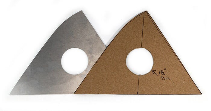
Our process works well not only for the outer contours of your part, but also for interior holes or cut features. We can smooth out the rough or imperfect edges of a circular cut, but if you need the hole to be a specific size, please note it as clearly as possible on the template itself. To this end, you may find it easier to use a small hole to demark the location of a larger one; it is easier to create a hole using a punch set than it is using scissors. By adding a small hole with the same center location as the larger hole you need, it allows us to add the feature directly to your CAD rather than requiring us to reach out for location dimensions.
In the example below, a ½” hole was used to locate a hole that actually needs to be 1.5”. When using smaller holes to locate larger ones, it is imperative that the hole be located with the same center location as the larger one, or that its dimensions are clearly called out on the template itself.

Some templates are too large and bulky to economically or safely ship. If your template is large enough that it needs to be bent for shipping, there are a few things to keep in mind.
Depending on the level of accuracy needed, you may find that cutting the template and then joining the seam with tape is a better solution than folding the template. This is because cardboard can deform when folded. When taping a part, use quality tape that won’t peel off during shipping. Packing tape and wide masking tape work well, while scotch tape, electrical tape, and blue/green painter’s tape can be problematic.
If you choose to fold your template for shipping, that’s okay too!
While we need your physical template to be flat, we’re happy to add bends to your design after we’ve created the CAD from your template!
There are a few things to consider when adding bending to a part, but we’re happy to help you with them.
The first thing to consider when adding bending to your design is the stretching that the material experiences during the bending process. It is preferable to know the desired outside dimension of your bent part rather than where the bend needs to happen on your template. Each material and thickness we offer will require that the bend line be in a slightly different place based on your finished, outside flange dimensions. If you know the bend location based on your material and thickness, we’re more than happy to add a bend line there, but if you don’t have that data, we can help there, too! Just ask us, or you can check out our Bending Calculator.

The second thing to consider when adding bending to a project is bend constraints; we have minimum flange requirements for each material, along with bending limitations that you’ll need to be familiar with. You can find the minimum flange requirements for each material and thickness on our Materials Pages, and you can learn more about our bending guidelines here. As always, if you have any questions about the feasibility of your design, please reach out to our support team.
While it may be tempting to send us the part that you need to be reversed rather than a template, please do not send anything except cardboard, posterboard, or gasket material. We cannot be responsible for parts that are lost or damaged in transit, and we’d hate to have your irreplaceable part damaged or lost on its way to or from our shop.
If you have a physical part rather than a template, please trace the part onto posterboard and cut it out. If you need the parts offset to account for the width of your pencil tracing, let us know how much offset you’d like during the intake process.
When we receive your initial template photo, we’ll do our best to check for issues that may prevent your design from being cut, bent, or otherwise processed. There may be things that we won’t be able to see until we process your scan, but in the event that we encounter a DFM (Design for Manufacturing) issue, we’ll work with you to find a way to process your parts.
We request a picture of your template for a few reasons, but the primary reasons are listed below:
We will check and confirm your template photo as quickly as possible to get your project in motion.
nce your part arrives, we can typically convert it in 1-2 business days.
Our reversal process is best suited for flat, soft parts like cardboard, poster board, or gasket material. We ask that no part be thicker than .25”. At this time, we do not accept metal parts or templates for conversion.
Unfortunately, we cannot do a physical conversion of a hand sketch or computer printout. The template needs to have all cut features removed from the parent material in order for the template process to work correctly.
Our maximum scan size is 30” x 44”.
Yes, we can! We’ll scan your part to within .003” of it’s physical size, but we’d be happy to smooth out the edges, holes, and other cut features for you. Please specify important hole diameters and other dimensions so that we can be sure to maintain those in the finished file.
No problem! We’ll flatten your template down during the reversal process, so that won’t be an issue. We’ll need to know the outside flange dimensions of the part, though, to ensure that all critical dimensions can be replicated for the final design in your selected material. The best way to do this is to provide a sketch of the part showing the finished, bent dimensions. Bend dimensions should be shown from the outside of the part.
We require that templates be sent in for reversal rather than metal or plastic parts because we cannot always return the templates to you. We cannot be responsible for items lost or broken in transit, and we hate the idea of your priceless part being lost on its way to or from our shop. Tracing the part on cardboard/posterboard and cutting it out with scissors or a utility knife will yield a template that we can use to create a CAD file from.
Our process can create CAD from your template that is within .003″ of your physical template. The best way to get a CAD file that matches your design is by creating the most exact template possible and following our Design Services guidelines for templates.
Depending on your design, you may want to consider submitting a dimensioned sketch instead if necessary details are difficult to reproduce when using cardboard.
Our materials and services have tolerances that can impact your finished part. We recommend taking production tolerances into account before finalizing and submitting your template. Learn more about SendCutSend material and process tolerances.
A minor revision may be requested once a CAD file has been created. The revision must not affect the overall design of the CAD file in a way that will require a redesign of any related features. Any major modifications will require further assessment and an additional design fee.
No. Due to the large number of variables that must be addressed in order to create a gear or sprocket, we will not be able to offer any design services for them at this time.
Yes, we can! First, you will need to add your parts builder design to your cart and save that cart. You can then send us a request with the cart number and a fully-dimensioned drawing of the desired modification. We will take it from there!
For copyright purposes, we can only convert drawings made by the customer requesting design services. If you can provide a fully dimensioned drawing of the part that you need, we will be happy to help!
If your idea does not meet these requirements you can check out our list of Design Partners to find someone that can assist you