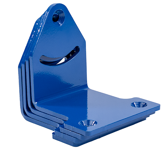
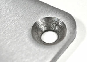
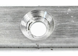
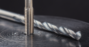
Countersinking protects your hardware from long-term wear by allowing the head to sit flush against the surface of your part. Pair it with our hardware insertion services for full assemblies.
High precision
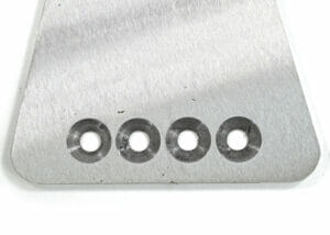
Achieve accuracy within ±0.015", ensuring a perfect fit for your hardware.
No minimum order
Whether you need one part or a thousand, we’ve got you covered.
Quick turn-around
Countersinking adds just 1–2 days to standard production.
“I had to do some post processing to get countersunk holes that I needed… parts were clean and accurate. Saved me a lot of time.”
Ethan B.
Available materials for Countersinking
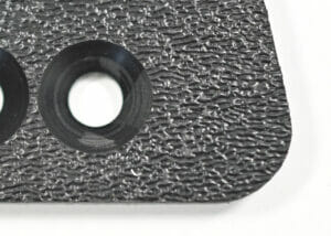
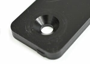
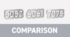
Our countersinking service is compatible with four aluminums and three plastics. Materials must be at least 0.125″ thick.
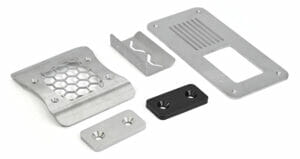
One step to a finished part Built to take abuse Looks as good as it performs
Following a few basic design guidelines will help ensure your parts are countersunk properly and pass SendCutSend review.
CAD setup & hole requirements
Draw only the minor hole in your CAD file
Do not include the major diameter; the countersink is machined to the correct size automatically.
Holes under 4″ are automatically resized You are responsible for ensuring adequate edge clearance and spacing between features after resize.
Countersink direction matters Countersinks can be applied from the top or bottom face. Use the 3D preview in the app to verify orientation before ordering.
Do not include the major diameter in your drawing
Countersink sizing & geometry
Major diameter
Should match fastener head diameter (~50% larger than minor hole). Do not include in your file
Minor diameter
Defined by your CAD file, must match intended fastener size
Max countersink depth
Should not exceed 60% of material thickness
Countersink angle: 82°
Standard for imperial/SAE hardware
Countersink angle: 90°
Standard for metric hardware
Contact requirement
Aim for ≥ 50% contact between hardware and countersink
Accuracy
±0.015″
Countersink size reference charts
82° (Common for Imperial/SAE bolts) Major/Minor/Depth Chart
File is in a format that we accept (2D: .dxf, .dwg, .ai, .eps; 3D: .step or .stp)
All holes and cutouts are at least 50% material thickness for laser cut parts
All holes and cutouts are no less than 0.070” for most waterjet cut parts
All holes and cutouts are no less than 0.125” for all CNC routed parts
File is built at a 1:1 scale, preferably in inch or mm units
2D files: all objects on the same layer, text converted to outlines, no open contours, all shapes united or merged, floating interiors bridged or stencilized
3D files: single solid sheet metal body, uniform thickness with a face at every edge, modeled at stock thickness with matching bend specs
All stray points, duplicate lines, empty objects and text areas have been removed
SendCutSend reviews
Customers love getting their sheet metal parts from us
AMAZING EXPERIENCE! From an idea I sketched on a piece of paper, to the part I needed already installed in my truck. Thanks to the AI tool, I think the whole project took me 30 minutes of work? I can't be more satisfied. Will absolutely come back
Posted on Google
Aaron Zhan
June 30, 2026.
Awesome service, shipping was fast, parts were spot-on.
Feels great to support a US-based company as well.
And parts were priced in a super reasonable manner.
Posted on Google
Mark Washenberger
June 30, 2026.
Tried it once so far, and it went great. I was able to get something working using Inkscape and a free 2D cad program for last step cleanup. If you're doing a bent part, study the information they have about bend radius and dimensional stretching carefully. Also their support was very helpful for me and gave me some advice that helped to make sure the part came out perfect the first time.
Posted on Google
Jonathan Liu
June 30, 2026.
Good job on the sheet metal parts I order with good price and short lead-time.
Posted on Google
CEG in NC
June 30, 2026.
Quick, accurate, easy-to-use service! Well done!
Posted on Google
Justin Drentlaw
June 30, 2026.
I ordered from SendCutSend online and the experience was straightforward and pleasant. The parts arrived a few days later and met my specifications exactly. I would definitely order from them again.
Posted on Google
Ion Albu
June 29, 2026.
Excellent! High quality, fast, affordable. Thank you SendCutSend!
Posted on Google
Minutemen Concepts
June 29, 2026.
Excellent work, excellent least times, and excellent website
Posted on Google
Tom
June 28, 2026.
Got what I wanted, clean, nicely packaged,fast, and at a fair price.
Thanks SCS.
Posted on Google
Nate Crosno
June 28, 2026.
Fast service, good pricing, and a great website. I get my first order and will be back for more. I am excited about the possibilities this opens up.
Please note: Pricing examples on our website are provided as general estimates and may not always reflect current prices. While we strive to keep these examples accurate, uploading your file is the best way to see instant current pricing.
Start your first SendCutSend project today!
Upload your CAD design, or try one of our customizable part templates to get instant pricing on your custom laser cut parts. All delivered to your door in a matter of days.