There are times where importing a picture into a CAD software can be a useful thing. One example is in providing unique features or images that can be traced over for a logo sketch. Laser cutting a logo into a part is a great way to simplify a design by eliminating the need to add extra parts or labels.
Another example is prototyping. In some cases, an irregular flat part may have been prototyped from a piece of cardboard, and the next step is to make the same part out of metal. Instead of needing to take numerous amounts of measurements to re-create the design in CAD, one could simply take a picture of the flat prototype piece, import the picture into a CAD program, and trace over the picture to recreate it in a CAD space.
This article will outline how to import an image into SolidWorks, create a sketch that is traced from the image, and properly scale the final sketch.
Importing an Image
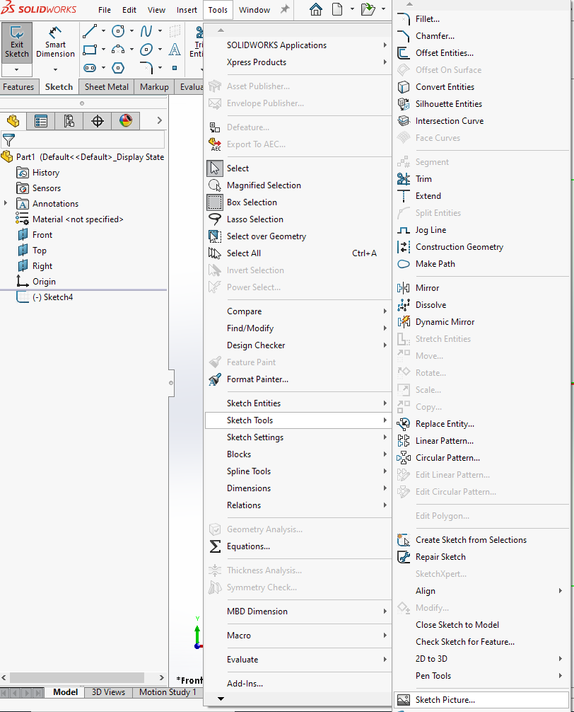
To import an image, first make sure that you are in a sketch view. In the sketch view, navigate to the tools menu and go into “Sketch Tools” and “Sketch Picture”. Once you click on “Sketch Picture”, select the image file that you desire, and click on the green check mark to finish the import. This takes you back to the sketch view.
Sketching Over an Image
In the sketch view, trace over the image to create the desired sketch. The figure below shows the image with a sketch traced over it.
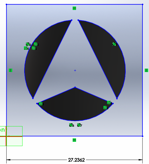
By dimensioning the sketch, it’s possible to see the size of the sketch. This likely will not match the desired size, therefore scaling of the sketch is necessary. Take note of the dimension so that the sketch can be properly scaled by the correct factor.
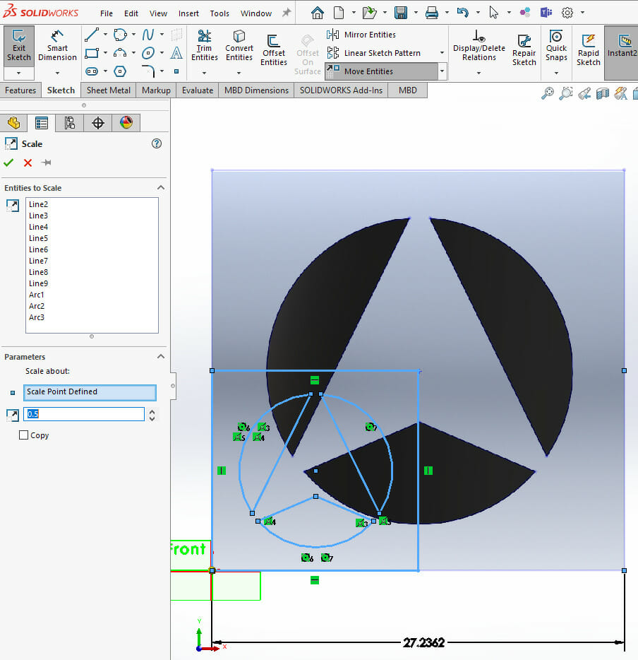
Scaling a Sketch
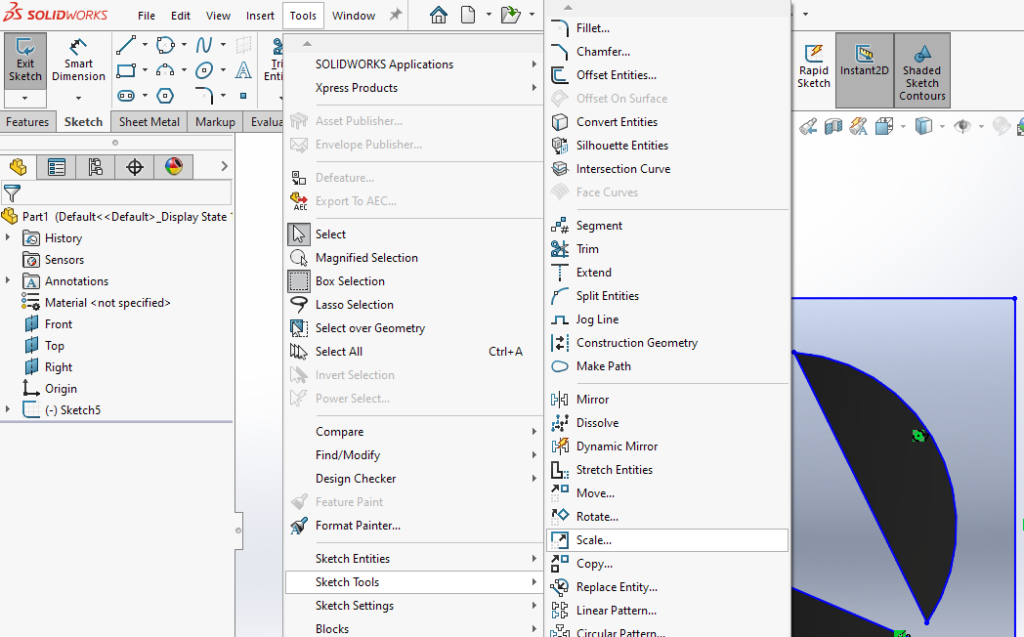
Delete the dimension so that the sketch can be scaled without the dimensional constraint interfering. After that, in the sketch view, go back to the tools menu and “Sketch Tools”. Select “Scale”. Draw a box around the entire sketch to prescribe the entities to scale. Finally, select any point to scale about, and prescribe a scaling factor in the appropriate box. Here, a scaling factor of 0.5 is used as an example.
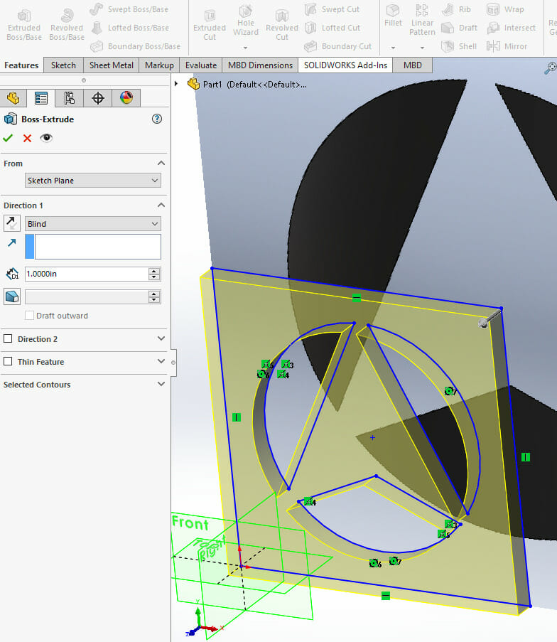
Create a 3D Part
Once the sketch is correctly scaled, extrude the sketch to create the part. To review how to extrude a sketch, review our article on Creating a 3D part in SolidWorks. Also review SendCutSend guidelines for minimum sizes of radii for different materials. Some materials may not allow for the laser to cut sharp corners into the material. Therefore, for some materials, this design may need to have rounded corners instead of the corners that come to a point.
Use the techniques in this article as additional tools in your SolidWorks toolbelt whenever you need to create a sketch of an existing image. Or, if you already have a flat, irregular design in your possession in a particular material, use this technique to bring it to life in another material.
Check out our blog from more SolidWorks tutorials.
Try our SolidWorks Plugin
If you are using SolidWorks 2021 or newer, check out our SolidWorks Plugin. You can upload to SendCutSend and get live quotes without ever leaving SolidWorks.
