
Designing bent sheet metal parts can be one of the more difficult processes in manufacturing. It may feel daunting learning how to set up your file for sheet metal bending, but in our years of machining and fabrication, we’ve found a few file setup tricks! These will help you get the best possible outcome from our sheet metal bending service.
From choosing the correct bend indicator in 2D files to modeling in 3D formats, we’re covering what you need to know about setting up your file for sheet metal bending. As always, be sure to read our bending guidelines as well before uploading your part!
All bent part files should be in formats we accept
When you send us your bent sheet metal or plastic design, we first have to laser cut or CNC route it depending on the material. Be sure to check the guidelines for the cut method that will be used for your part and ensure all cut geometry meets our minimum requirements for the material.
Most supported CAD modeling programs have sheet metal rules, which is what you should be using to design your part. It’s critical that you set up sheet metal rules using SendCutSend’s bending specifications for the material thicknesses you need. Each material thickness has a set internal bend radius and K factor that cannot be changed. If you don’t use our bending specifications in your design, your final part is unlikely to turn out as expected. You can find our bending specifications for each material thickness in our Material Catalog or handy chart.
If you will upload a 3D file, save your design as a STEP or STP format file and ensure it meets our 3D File Guidelines. With STEP/STP files you don’t need to worry about bend lines. Please model your flanges the way you’ll want them bent before exporting.
When working in a 2D design software, use our Bending Calculator to ensure your flat pattern results in the formed dimensions desired. If uploading a 2D file, save or export your file in one of these vector formats: DXF, DWG, EPS, or AI (Adobe Illustrator).
Our preferred CAD program is Autodesk Fusion, which is completely free for hobbyists. If you are designing your bent part using Autodesk Fusion’s sheet metal feature, you can either export your design as a STEP file or a DXF file.
Exporting modeled bent parts to STEP from Fusion
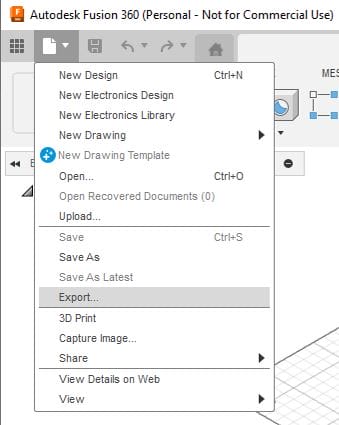
With your 3D part modeled in Autodesk Fusion, navigate to File > Export.
This will open the Export window. Name your file. Then, in the Type drop down menu, choose STEP Files (*.stp *.step).
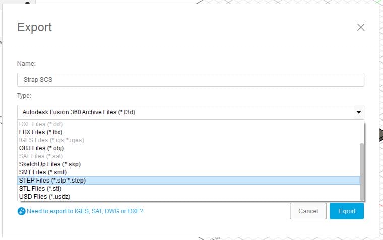
Confirm the location you want to save your file to. Then click Export.
You should see a notification from Fusion in the upper right hand corner indicating that your STEP file export is ready!
Exporting modeled bent parts to DXF from Fusion
While exporting modeled parts to the STEP format is a quicker process, exporting to DXF is a good alternative if your STEP file meets our bending guidelines but still receives errors. You’ll see an open entities error if your part is not set up using our bending specifications. Double check that the bend radius and K factor are correct before exporting a DXF instead of a STEP file.
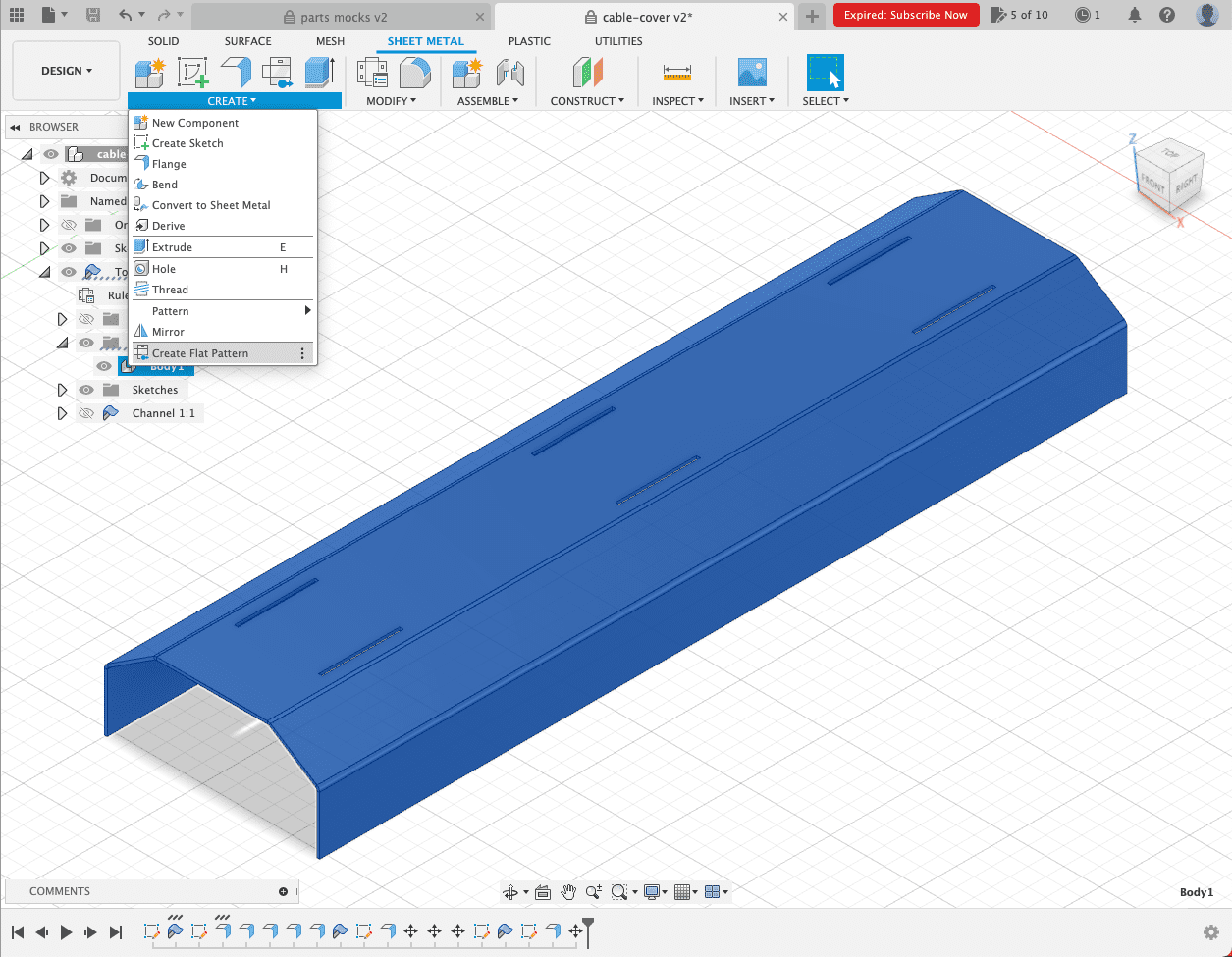
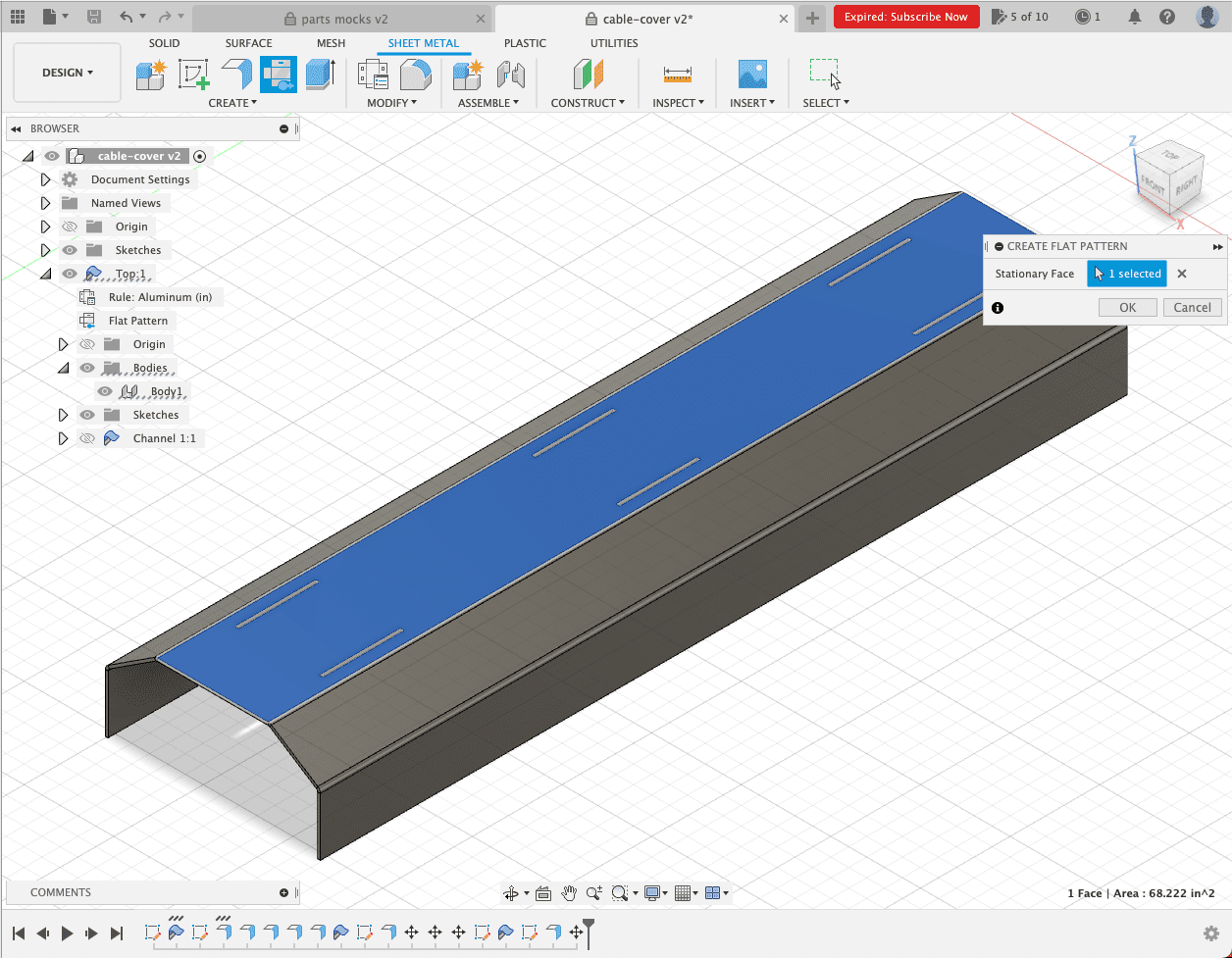
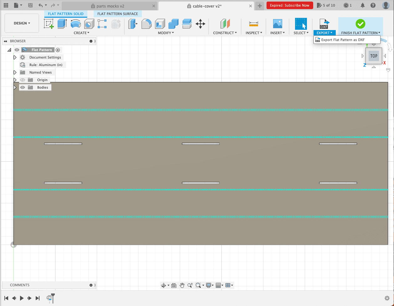
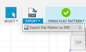
With your 3D part modeled in Autodesk Fusion, click “Create Flat Pattern” underneath the “Surface” option. With that open, you need to select the stationary face of the part that all your flanges are bent from. When you are finished with that and select “OK,” you’ll see your part laid flat with all bend lines already included. This is what you will export as a .dxf and upload to our website.
Do not leave notes anywhere in your file to indicate the direction of the bends or their angles. You will be able to indicate bend angles and directions when you upload your file for quoting, so there’s no need to leave additional notes.
Choosing the right bend line indicator for 2D files
For 2D format files, you will need to put bend lines in the file to indicate where we should bend your parts. There are a few different ways to indicate bend lines, and each software you use requires something different.
If you followed our above instructions for Autodesk Fusion, the bend lines will appear automatically with the “Create Flat Pattern” function. They will default to a solid line, which is our preference for bent sheet metal parts designed in Fusion. To achieve correct bend lines in Autodesk Fusion, you will need to define the dimensional thickness of your part, convert it to sheet metal, create a flat pattern (as shown above), export as a .dxf, and in the “Export as a .dxf” dialogue, select “Convert splines to polylines.” This will result in 3 solid lines to export. The center line will automatically be detected in the SendCutSend app for bending.
All programs have different methods for indicating bend lines, so refer to this chart to see what style we prefer based on which software you use.
| SOFTWARE | 2D FORMAT | BEND LINE |
| Fusion | .dxf | Solid line (default) |
| Adobe Illustrator | .ai | Solid, separate color from cut lines |
| SolidWorks | .dxf | Dashed line (default) |
| AutoCAD | .dxf | Dashed line |
| CorelDraw | .eps | Solid, separate color from cut lines |
| Inkscape | .eps | Solid, separate color from cut lines |
Final sheet metal bending considerations
As you’re setting up your file for sheet metal bending, there are a few final design things you should keep in mind:
- Keep all features and holes outside of the width of the die that will be used to bend your parts. The minimum distance and die used changes based on what material and thickness your bent part is using, so check the material bending specifications to ensure any cutouts are far enough away from the die line. This will prevent warping on your part. See our Bending Deformation Guidelines for more information.
- We do not offer cosmetic protection for your parts during bending, so you may see die marks from the bending process. You can remove these fairly easily with a random orbital sander.
These are just a few design considerations to know while setting up your file, so read our full sheet metal bending guidelines before uploading to our website. And if you have any questions at all, our support team is always here to help you find the answer.


