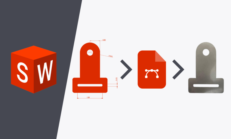
In this tutorial, we’ll go over how to use SolidWorks to create a 3D part from a 2D sketch. This article is part two of our two part series, “A Beginner’s Guide to SolidWorks.” To follow along with the tutorial from the beginning, check out the first article in the series, “Introduction to SolidWorks: How to Create a 2D Sketch.“
Before you begin, check out our SolidWorks Plugin. You can upload to SendCutSend and get live quotes without ever leaving SolidWorks.
Extruding a 2D Sketch Into a 3D Shape
With a 2D sketch, it is quite easy to create a 3D part in SolidWorks. At the top of the screen towards the left of the ribbon, there is a tab called “Features.” Select that tab and then select “Extruded Boss/Base.” This extrudes the 2D shape into a 3D shape. The design tree changes and gives you the option to specify the depth of the extrusion. This can be thought of as the thickness of the part.
For the purposes of this tutorial, the depth is kept at 0.1 inches. Click the green checkmark in the design tree to finish this step. The part is now 3D. If you press the wheel on your mouse while moving the mouse, the part moves in 3D space.
Sketching on a 3D Part Surface
To match the bracket in the project, it is necessary to add holes to the 3D part in SolidWorks. This is done by first creating a sketch of the hole on one of the surfaces of the part.
To do this, navigate back to the sketch tab. Select the “Sketch” icon. The design tree now asks you to select a face on which to create the sketch. Select one side of the part as the face. Next click the axis (at the bottom left of workspace) that is perpendicular to that face. This will reorient that face into view. After that, go to the “Circle” icon and select “Circle.” Unlike the “Perimeter Circle,” Circle works by placing the center point of the circle with the first mouse click, followed by assigning the radius after dragging and clicking a second time. Draw a circle at the top of the drawing, roughly estimating its location and size. Again, the philosophy is to create lines or sketches first, and then add dimensions later. After creating the circle, create a narrow rectangle in the bottom section of the bracket part. Click the green checkmark in the design tree to finish this step.
Centering and Alignment
Continue the hole sketches by refining their placement. Start by making the circle concentric with the rounded top of the part. Select both the edge of the circle and the edge of the rounded top of the part. Do this by clicking on the circle edge, followed by holding “Ctrl” and clicking the edge of the rounded top. The design tree appears with new options. Select “Concentric” and observe how the circle is re-positioned to be perfectly centered with the rounded edge.
To center the narrow rectangular sketch, hover the mouse cursor over the midpoint of one of its long edges. Notice a small square appearing. This denotes that you have found the midpoint of the edge. Click that point, and use “Ctrl” to select the center point of the circle at the same time. Notice the design tree appears with new options. Select “Vertical” to vertically align the narrow rectangle and the circle. Observe how the narrow rectangle is re-positioned to be nicely centered with the circle. Click the green checkmark in the design tree to finish this step.
Next, finish the position of the narrow rectangle by choosing to horizontally align one of the short edges with one of the adjacent vertical lines in the bottom of the part. After that, finalize the size of the sketches. Using the same dimensioning methodology as before, assign height and width to the narrow rectangle. Similarly, assign a diameter to the circle. Click the green checkmark in the design tree to finish this step.
Using the Extruded Cut Feature to Create Holes
Now is the time to cut holes! Select the “Features” tab, click on “Extruded Cut,” and then use the drop-down menu for the direction of the cut in the design tree to select “Through All.” This makes sure that the cut is indeed through all the material, and not a blind hole. Click the green checkmark in the design tree to finish this step.
Using the Fillet Feature to Round Sharp Edges
Finally, the last step to creating a 3D part in SolidWorks is rounding some of the edges of the part to get rid of sharp corners. This can be done using a feature called “Fillet.” While still in the “Features” tab, select the “Fillet” icon located near the middle of the ribbon at the top of the screen. Then, select all the outer edges that need to be rounded. Press the mouse wheel to move the part as needed. Use the “Ctrl” keyboard button if more than one edge needs to be selected. Once all edges are selected, specify the radius of the fillet in the design tree. Click the green checkmark in the design tree or press enter to finish this step.
We are rounding the outer corners on this part for the purpose of this tutorial, but adding fillets is not always necessary and you will need to decide for yourself whether or not your part requires rounded edges. Keep in mind that all internal geometry will have rounded corners and edges if the part is being cut on the CNC router or waterjet cutter, so be sure to check how your part is being machined based on what material you use. You can find this information in the “Design Considerations” section of the materials pages.
Repeat the process to round the edges on the inside of the narrow rectangular hole. For these edges, the radius needs to be smaller than the edges on the outside of the part due to the narrow hole. If the radius is made too large, the narrow rectangular hole will have strange edges due to the overlap of the rounds if they become large enough. Therefore, the radii of the inside edges are specified to be 0.05 inches. The radii of the outside edges are specified to be 0.10”.
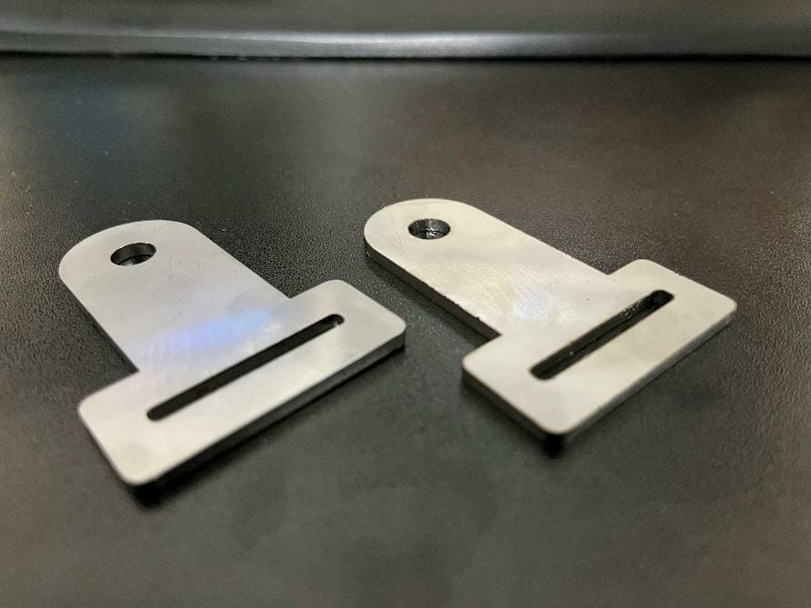
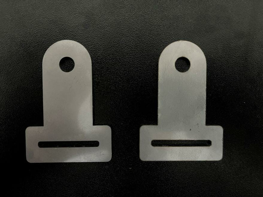
Bringing a 3D CAD Part to Life
To prove the CAD design and bring it to life, a DXF file was exported from the design of this tutorial and we cut it right here at SendCutSend. As shown in the pictures below, SolidWorks drawings do an amazing job at envisioning the real-life manufactured part, assuming high quality and precise manufacturing. SolidWorks (and CAD in general) is a wonderful tool for virtual prototyping and design.
Benefits of CAD and SolidWorks
CAD in general has the ability to produce accurate 3D designs. This greatly reduces the chances of later errors like poorly constrained prototypes, sloppy proof of concepts, and ill-fitting parts in assemblies. Knowing how to create a 3D part in SolidWorks is a powerful tool for the hobbyist, designer, or manufacturer!
You can export your 3D CAD files to either 3D .step format files or 2D .dxf format files.
If you export your design as a STEP file, make sure it meets our 3D File Guidelines.
If you want to export a DXF file, check out our article on exporting a 2D DXF and our other SolidWorks tutorials as well.
