PTC Creo is an industry standard CAD software, especially among roboticists. Exporting from Creo is rather complicated with SendCutSend so it is not our preferred software; we highly suggest using softwares like Autodesk Fusion, AutoCAD, or SolidWorks. But if you’re using Creo for your laser cutting, follow this video and guide to make the process more straightforward. We’ve broken it down into 17 simple steps so you can easily learn how to export in PTC Creo from start to finish.
Video Guide for How to Export in PTC Creo
Export in PTC Creo from Start to Finish
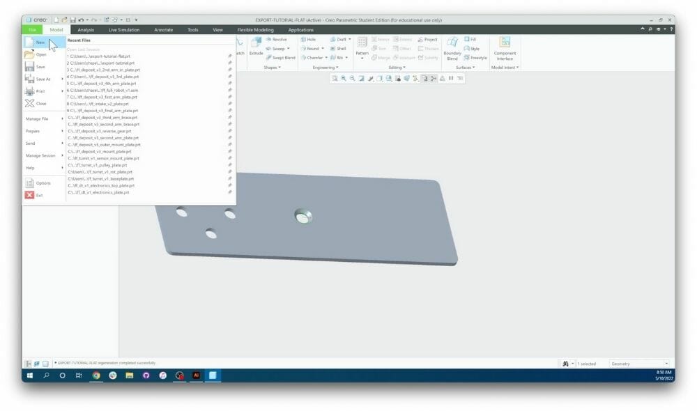
Step 1: Open new file
With the part you want to export open, click “File”, then click “New”
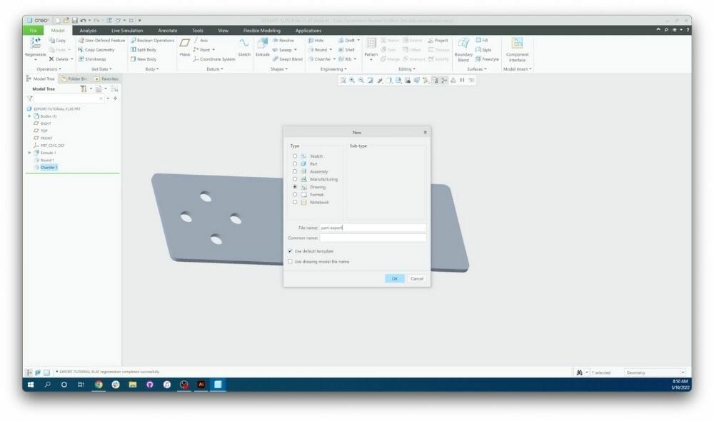
Step 2: Create new drawing
Select the “Drawing” option. Name the drawing and select “OK.”
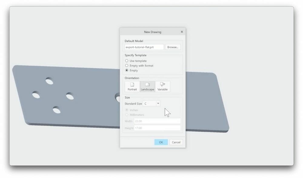
Step 3: Adjust template size
Under “Specifying Template,” select the “Empty” option. Then change the orientation and size to ensure that the width and height listed at the bottom of the dialogue box are larger than the footprint of your part. If necessary, select the variable option and change the dimensions as needed. There is no harm in making the template too large.
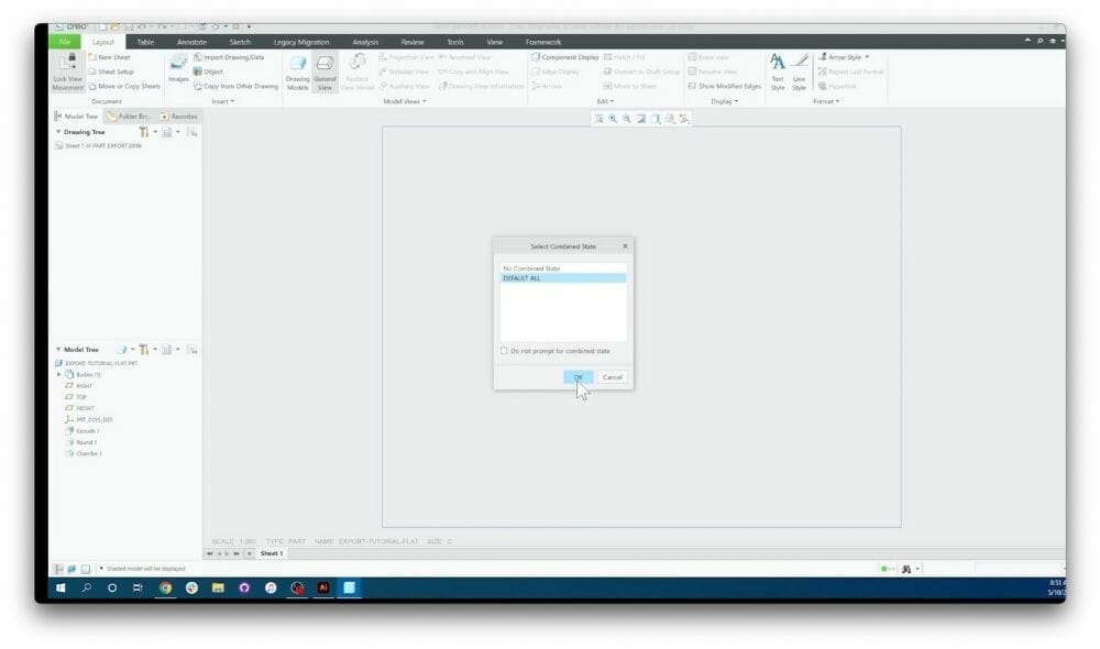
Step 4: Set default values
Now you’ll be presented with a blank window with a blue box on it. Select the “General View” option in the toolbar. Then select DEFAULT ALL and click “OK.”
Step 5: Open “Drawing View”
Double click your mouse anywhere in the large blue box and your part should appear. You should also have the “Drawing View” dialogue box on your screen.
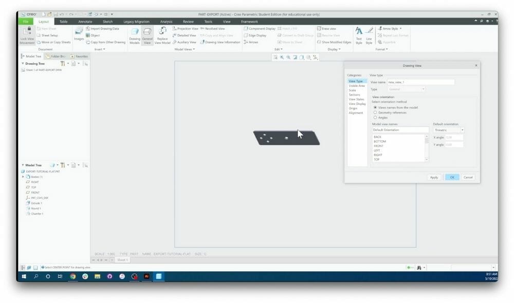
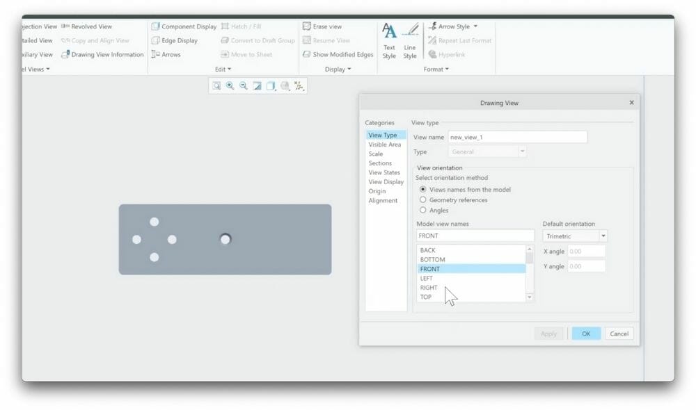
Step 6: View part in correct orientation
Under the “View Type” category, you’ll need to cycle through the list of views until your part is in the correct orientation. Usually, either the FRONT or RIGHT view is the one you need. Click “Apply” to ensure it is the correct view.
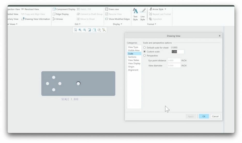
Step 7: Scale file to part in 1:1
Now select the “Scale” category on the left side of the dialogue box. Here you’ll want to make sure that your scale is set to 1:1. If that is the default, you don’t need to change anything. Otherwise, set the “Custom Scale” to 1 and click “Apply.” This is important as it determines the dimensions of your part when it is exported. For example, if your scale is set to 0.5, your part will be half the size it’s supposed to be.
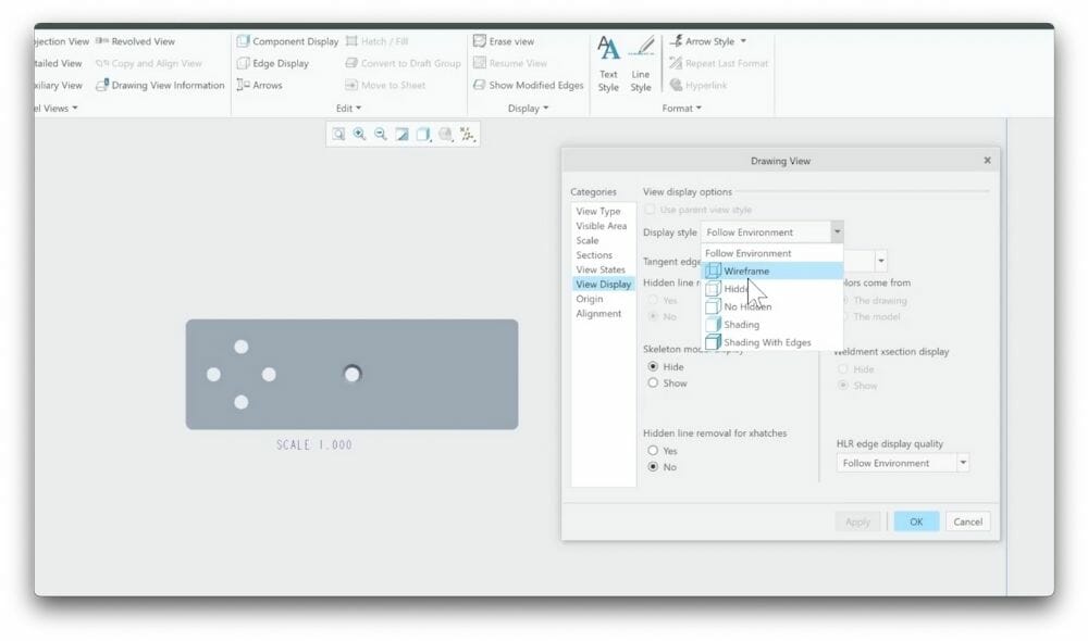
Step 8: Apply display style
Now move down to the “View Display” category. Here we are going to change the display style to wireframe and click “Apply.”
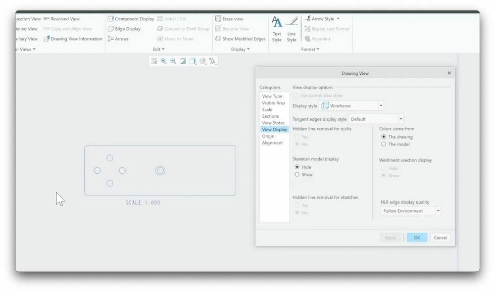
Step 9: Check part outlines
Once you click “Apply,” your part should only have outlines of all of its edges as shown here. If this is not the case, retrace your steps to see if anything was done incorrectly or in the wrong order.
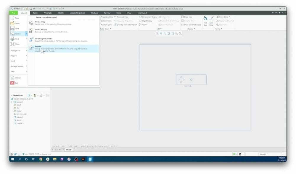
Step 10: Export file
This is the last step to export from Creo. After this, you’ll be using another program to clean up the file. Close the last dialogue box by clicking “Ok.” Click “File,” hover over the “Save as” option, and click “Export.”
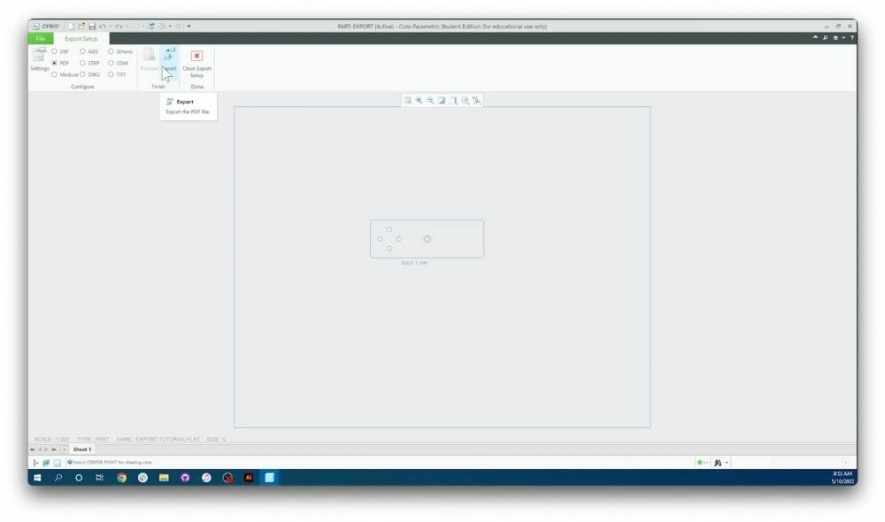
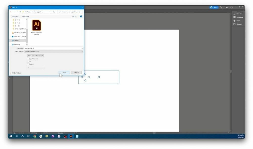
Step 11: Select file format
You’re ready to choose your file format. Which file format you choose will depend entirely on the software you are going to clean up your drawings in. We highly recommend using QCAD as it will produce the most reliable result. QCAD is a free, open-source 2D CAD program in which you can check all of your geometry and remove extraneous information. To export from Creo for QCAD, use a DXF file format. This is our most recommended method for cleaning up a file from Creo, and all other methods should be used as a last resort. For this example, we will export as a PDF to clean up in Illustrator and save it locally to our computer by clicking the export box.
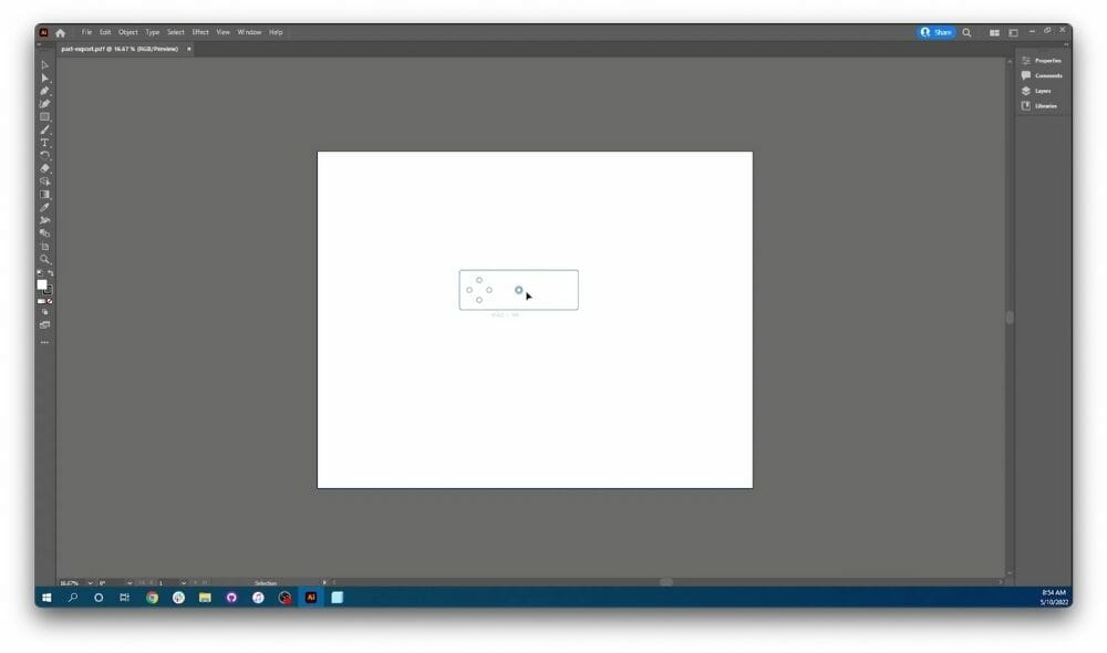
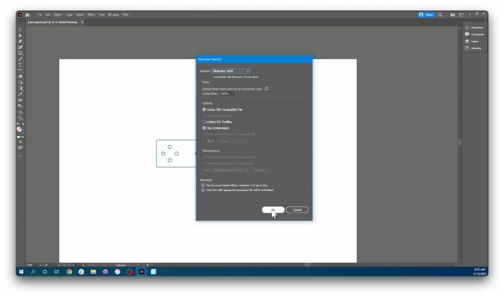
Step 12: Open file in new software
Open the file you just exported in Illustrator or your respective software to clean up any errors that may have occurred while exporting from Creo.
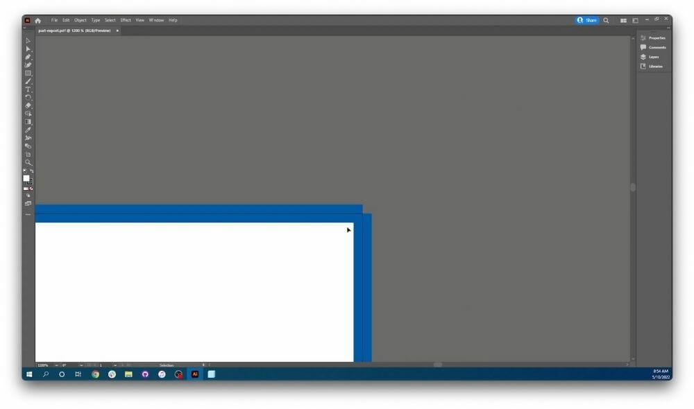
Step 13: Remove Creo bounding box
If you zoom in on the corners of your canvas, you’ll notice that the blue box you saw in Creo carried with the design drawing during exporting. If this box is left in the drawing when you send it to be laser cut, the laser will cut the outside box in addition to the part itself. Because of that, it’s important that it be deleted. In order to delete the box, highlight the outside border of the canvas one side at a time and click delete on your keyboard to ensure that no line is left behind.
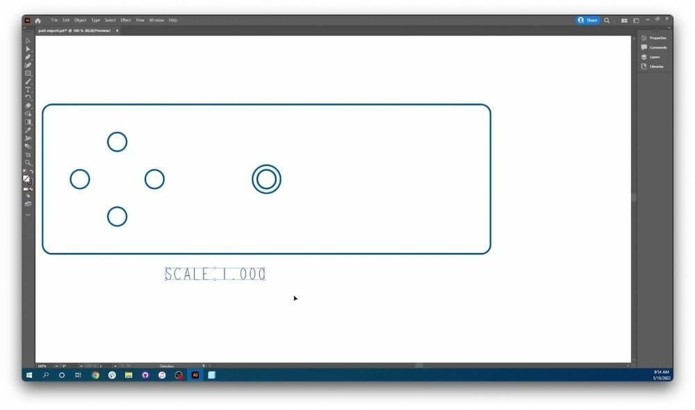
Step 14: Remove Creo Scale Marker
Now you’ll need to zoom in and do the same thing for the scale reference at the bottom of the part. If you didn’t have to change the scale in Creo, you probably don’t have one of these boxes and that’s fine. But if you do have the Scale Marker, highlight and delete it. Ensure that you selected the entire piece of text.
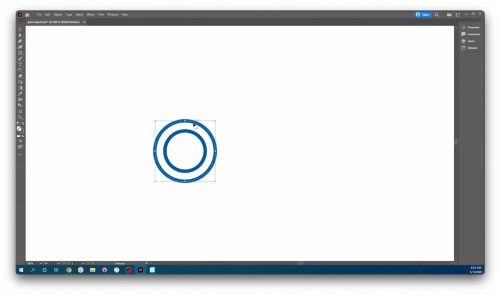
Step 15: Remove bad geometry
If you have countersink holes or any sort of concentric/cascading cuts, be sure to remove the outside shell. With a countersink, for example, you’ll end up with a much larger hole if you leave the line from the chamfer in as it’ll cut a hole where the countersunk recess is supposed to be. Therefore, you’ll need to select each one of these outer rings and delete them.
Step 16: Export file
Click File, Save As, and save your file. Again, what file type you save depends on what program you’re using. Refer to the table below to see what kind of file you should be exporting:
| Adobe Illustrator | .ai |
| AutoCAD | .dxf |
| CorelDraw | .eps |
| Fusion | .dxf |
| Inkscape | .eps |
| SolidWorks | .dxf |
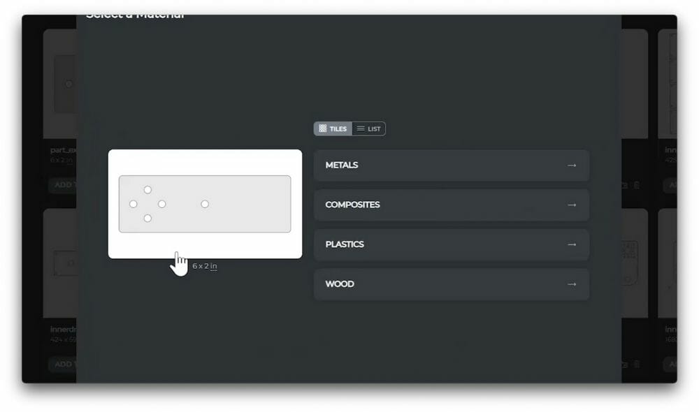
Step 17: Get instant pricing and order!
Upload your part to the SendCutSend instant pricing tool and check that your dimensions match the dimensions of your original part in Creo. If your measurements match, you are ready to order!
How to Export in PTC Creo and Other CAD Software
PTC Creo is not our preferred CAD software because it produces unreliable exports that are difficult to cut by the laser. We recommend using one of our recommended software, but if you’re using Creo, following the above steps is the best way to utilize Creo alongside other resources to make sure it works for manufacturing.
If you have questions about exporting from other software, we are continually updating our blog with resources to help you get the most out of your SendCutSend experience.
