Good prototyping is a core part of developing products quickly and effectively. Prototype iteration is limited by spend and speed. You want prototype parts quickly and affordably.
There is a way to easily reduce cost, manufacturing time, and risk for your prototypes. Instead of relying on manufacturing processes such as CNC machining, you can utilize 2D CNC cutting services, like SendCutSend that include CNC laser and waterjet cutting to quickly make prototype parts and assemblies. 2D cutting is not only faster to program, it’s also faster in machining time.
The Benefits of Designing for Manufacturability
Engineers are (should be) always designing for manufacturability. When done properly it reduces part cost, lowers risk, and increases manufacturing speed and the prototype iteration process. For this reason, the choice of how you manufacture your parts is critical even in the prototyping phase.
A process often relied on in prototyping is CNC milling; it can be slow, costly, and unscalable. Unless the engineer is totally aware of the tools and processes unique to the machine shop they’re manufacturing with, programming and tooling up these machines can be incredibly slow and costly as features in the part designed by the engineer may not be within the machine shop’s standard capability.
To make things worse, each time the machinist needs to communicate with the engineer, time and cost is added to the part. Even when the time factor is taken out of the equation, the process is still costly as milling multiple faces requires re-mounting the part within the machine and requires time and attention for each operation.
A Welcome Alternative to Costly Machining
An alternative to more costly machining processes are CNC cutting companies like SendCutSend that offer several CNC metal cutting services such as laser cutting and waterjet cutting – it is fast and affordable at limited run quantities and mass production scale. CNC milling even when specified by the engineer perfectly (rare) does not scale to mass production as milling multiple faces requires operator intervention.
These 2D cutting processes have less risk as they require no capex to produce the first run of parts. They can easily be scaled into mass production. Parts that are cast for example require heavy upfront capital expenditure in tooling and process development. CNC laser and waterjet cutting do not have these expenditures and can be quickly spun up to manufacture custom parts on demand.
Not only do these processes scale well, programming sent to these processes can quickly be modified to account for changing revisions of parts. As you iterate through changes to your prototype parts, you will need to relay changes to parts.
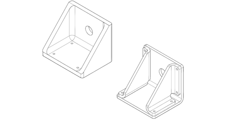
“But my parts are too complicated for 2D cutting” you may say. Not always true. See the example below of a CNC milled block of steel that was re-designed for 2D cutting.
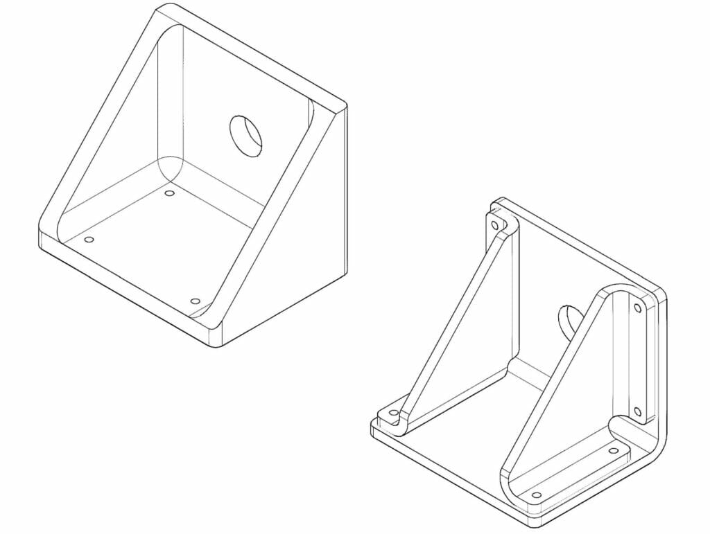
In figure 1, the block milled out of steel on the left requires mounting the part twice in a standard mill to manufacture. Additionally, the operations require removing a large portion of the material.
Conversely, the alternative designed using 2D cutting and forming operations is cheaper and simpler to manufacture. At the cost of increased number of parts (three versus one) and additional assembly time (four additional bolts to mount the two gussets) the cost, manufacturability and importantly scalability are greatly increased.
This new configuration of the part does not require future engineering time in the form of design for manufacturing. The parts are greatly reduced in cost (by more than 70%) as you scale the quantity higher and higher. This reduces engineering time required in the future and can greatly reduce the overall cost of your product.
To summarize: do not count 2D cutting out for complex parts. 2D cutting correctly paired with bending can yield complex shapes for both prototyping and mass manufacturing needs. Even better, SendCutSend can assist you for part runs from one to thousands, at the click of a button.
This article is a guest submission from Emanuel Moshouris


