In addition to laser cutting, SendCutSend’s CNC Bending Service can take your precision laser cut parts and literally bring them into three dimensions. Jumping from the 2D world into that third dimension does add a lot more math to the, uhm, equation, but our app does most of the number crunching so you can be confident that the part you get in the mail looks just like the part you made in CAD.
In this article we discuss:
• Common sheet metal bending pitfalls
• Tips for designing your bends right the first time
• How to avoid errors in the uploading process
• Visual examples of common bending mistakes
The 7 Most Common Sheet Metal Bending Mistakes
Few things are quite as frustrating as putting the sweat equity into designing a part, selecting the perfect material, getting the finish just right, and finally ordering the part, only to have it arrive with bends distort at the ends, caused cracking in the surface of the material, or warped the flanges till they’re not useful anymore. So let’s look at how to avoid these 7 common mistakes:
1. No Bend Relief
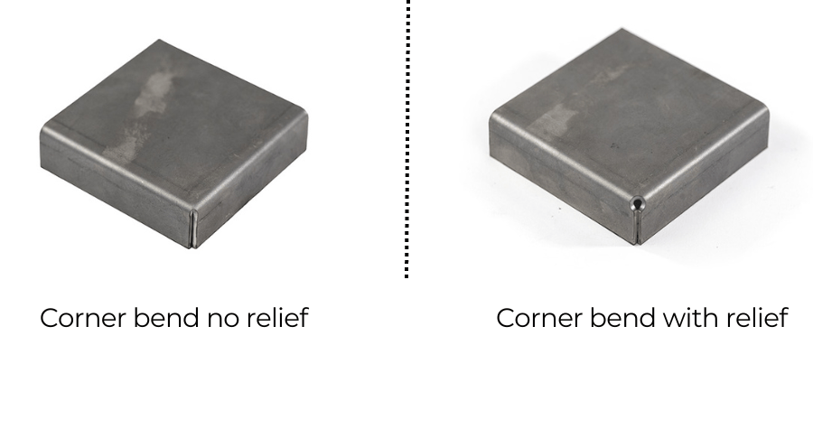
In sheet metal design, bend relief refers to a small cut or notch made at the intersection of two bend lines. Its purpose is to prevent material deformation, tearing, and other issues during the bending process.
Knowing that you need bend relief is a good start, but if it just serves as a transition from flat to bent, can’t we just make a slit (known as a kerf cut) and call it good? This article on how to design bend reliefs dives deep into what it is, and how to include bend relief in your design from the get-go.
What happens if you don’t add bend relief? Take a look at the examples below, and remember that bend relief is necessary to ensure both structural integrity and dimensional accuracy of bent parts. Without it, the metal can stretch unevenly, leading to distortions and potential failure. In more technical terms: bend relief allows for controlled material flow, minimizing the risk of tearing or cracking, especially in high-stress areas.
Fortunately, most modern CAD programs make it easy to incorporate bend relief before exporting your parts for upload to our app. We’ve pulled together a series of the most valuable resources on our blog in the following articles:
- Designing for Sheet Metal Bending with SendCutSend
- Guide to Solidworks Sheet Metal Bending
- How to Use the Bend Tool in Autodesk Fusion
- How to Design Custom Sheet Metal Parts in Autodesk Fusion
Knowing what makes up a good bend relief is dependent on your part geometry, thickness and material properties, so one size does not fit all, but having a good grasp on this topic will help you avoid:
- Stress Concentration
Insufficient bend relief can still result in high stress concentrations. These localized stresses can lead to minor deformations or create weak points that compromise the structural integrity of the part.
- Cracking and Material Failure
While insufficient relief might not cause immediate and obvious cracking, this zone, known as a “stress riser”, is still susceptible to micro-cracks or minor tears that can propagate over time. This gradual degradation can lead to premature failure, especially under repeated loading.
- Dimensional Inaccuracies
Parts with insufficient bend relief may not achieve the desired bend angles, particularly at right-angle corners. This leads to inconsistent results part-to-part even with CNC bending equipment, and potential assembly issues.

2. Not Calculating for Sheet Metal Bend Allowance
Bend allowance is basically the amount of stretch that the bend operation is going to add to your final part length.
We don’t typically think of metals in terms of how far they can be stretched, but in reality, when you put a piece of sheet metal in a hydraulic press brake, the amount of force exerted is enough to stretch the material significantly.
Take a look at this video, to watch Jake explain the basics of how the bend is in tension at the apex and compression in the corner.
Although any major CAD program will automatically calculate a bend allowance, it’s important to change the specifics of the bend to match the actual material and thickness of your material AND the geometry of our bending equipment. To simplify this process for you, we’ve put together a handy Bending Calculator that spits out the correct k-factor and bend radius. To use it with your CAD software of choice, follow these steps:
- Draw the part with the flanges in place using the sheet metal function
- Edit the bend radius to match the advanced details in the bending calculator.
- Adjust the K-factor or Bend deduction value to match that in the advanced details.
- Verify the part is correct by flattening your part and measuring the overall length and bend line locations in reference to the bend calculator layout.
3. The Importance of Flange Size in Sheet Metal Bending
Although CAD will allow you to make flanges in just about any orientation and length that you can dream up, when it comes to putting material in the brake, there are some very limitations on the length, width and spacing of your flanges.
Flange Height
In the simplest terms, on our CNC sheet metal brakes, the bottom die needs sufficient contact at two points on the part, so that the bend is successful and the part doesn’t slip off the die. Because the dies are sized for the material and thickness, the length of that span varies part-to-part.
For example, 0.250” stainless steel has a minimum flange length of 1.150″ before the bend, while a much thinner 0.040” aluminum sheet can be bent with a flange as short as 0.255″.
Fig.: Bending specs for 0.250” 304 Stainless. The Material Details for each can be found at the bottom of their respective Materials page.
Fig.: Bending specs for 0.040” 5052 Aluminum
Bend Length
The bend length, or width of the flange, is dependent on, wait for it, the material properties: For the 304 Stainless in the previous example, the maximum length is 36” while a thinner, more ductile material like the the 5052 aluminum can easily be bent all the way up to the max part size of 44”.
4. Bends Too Close
- Effects
- Material failure
- Difficulty in manufacturing
- Design Considerations
- Minimum distance between bends
- Adjusting designs for material properties/thickness
5. Sheet Metal Bending Collisions
Whether it’s an asteroid, a motor vehicle, or a sheet metal part, collisions really aren’t a good thing. In the world of bending, a collision occurs when the material to be bent contacts any surface other than the dies. There are two main flavors of collision:
Collisions with the Brake
These occur when a part’s geometry interferes with the bending process on the press brake. This can happen during the initial bend or when attempting subsequent bends, leading to contact between the part and the machine’s tooling or other surfaces.
Common Causes
- Incorrect bending sequence that causes earlier bends to interfere with the tooling during later bends. Our experts mitigate this by knowing where to begin each piece, ensuring that if it can be bent, they’ll bend it right.
- Parts with complex geometries that have multiple bends and don’t account for the machine’s capabilities and limitations. This one we can’t control, but we have lots of tips on how to avoid it on our website.
Self-Collisions
Self-collisions occur when different sections of the part interfere with each other during the bending process. This often happens in complex parts with multiple bends, where one bend causes a section of the part to collide with another section.
Common Causes
- Inadequate Spacing between bends, leading to overlaps or contact between different sections of the part. This is pretty well covered in the previous section.
- Design with the tooling in mind.
- If you’re working in 2D, once you upload the part to our App, you can see exactly what the bends will look like in 3D.
- Bend Sequencing: Incorrect sequence of bends that brings sections of the part into contact with each other prematurely.
6. Geometry Distortion
Geometry distortion refers to deformations or changes in the shape of features on your sheet metal part during the bending process. This can include warping of large cutout sections, stretching or ovalization of holes that need to be tapped in a following step, or misalignment of features that were intended to remain flat or in a specific location.
**Stolen from this article
Causes of Geometry Distortion
- When features such as holes, cutouts, or edges are too close to the bend line (die line), they are more likely to distort during bending. The stress and strain in these areas can cause the material to deform unpredictably.
- Flanges where there are unsupported points along the bend line (see the next heading for more on this).
Different materials respond differently to bending: Softer metals and polycarbonate stretch more easily, while harder metals are more prone to cracking or other types of distortion. This means that the spacing from feature-to-bend differs depending on the material and thickness. Always consult the Bending Specifications portion of the Material Details for what these values should be, and remember to confirm that your CAD software is using these same values when you design your part.
Check out this Bending Deformation article for lots of other examples and specifics on how to avoid geometry distortion.
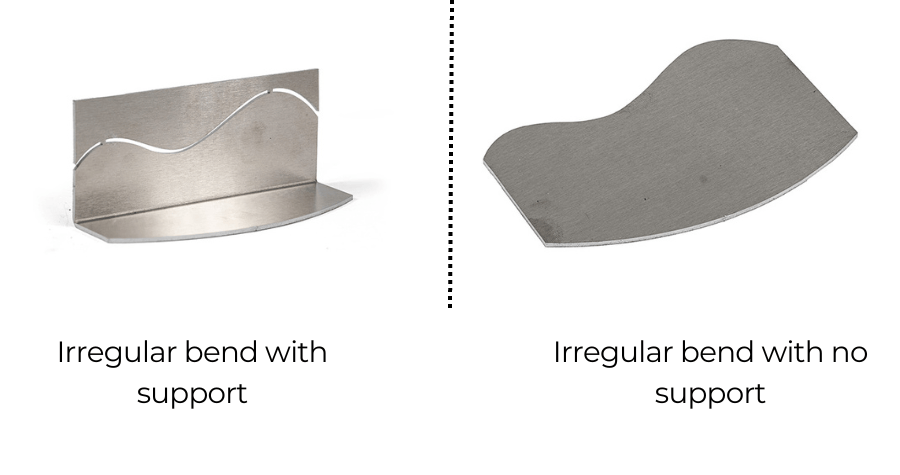
7. Bend Not Supported All the Way Across
Ensuring that the flange is fully supported across the bend is important when you’re looking for accurate bends. Even with CNC equipment, when a flange is not adequately supported during the press brake operation, several issues can arise, which affect the part’s dimensional accuracy, structural integrity, and overall functionality:
- Inaccurate Bends: When a flange is not fully supported, the applied bending force may not be evenly distributed along the bend line. This uneven force can result in bends that are not at the desired angle, leading to dimensional inaccuracies.
- Bend Line Deviation: Partially supported flanges may cause the bend line to deviate from its intended path. This can result in misalignment of features and holes, making it difficult to assemble the part correctly even if it passes an eyeball check.
- Springback Issues: Springback is the tendency of metal (and especially plastics) to return partially to their original shape after bending. Unsupported flanges can exacerbate springback, making it difficult to achieve the desired bend angle and increasing the need for post-bend adjustments.
If your design calls for a flange that has an irregular edge, or one that is not parallel to the bend line, take a look at this quick video about designing in a temporary reference edge so that the bends come out consistent:
Navigating the World of Sheet Metal Bending
Navigating the world of sheet metal bending might seem daunting at first, especially when transitioning from 2D designs to 3D parts. However, understanding and avoiding common pitfalls can make the process smooth and efficient. At SendCutSend, we pride ourselves on our CNC bending service, which transforms precision laser-cut parts into perfectly bent components.
This article focused on seven of the most common mistakes in sheet metal bending, providing provide practical tips to avoid them. By incorporating proper bend relief, calculating bend allowance accurately, and ensuring adequate support across flanges, you can be sure your parts will transition seamlessly from CAD, through our app, and into functional, high quality parts. As with all our services, if you are ever in need of a custom part outside of what can be uploaded to the app, a quote, or just have questions, reach out to our experts and we’ll get the job done.
Bending laser cut sheet metal allows for a broad range of custom parts to solve your design challenges, and at SendCutSend we make this Service quick and accessible, at just $19 minimum per order.

