We accept four different file types here at SendCutSend: .ai, .eps, .dxf and STEP. What file type we require depends on what software you’re using, and for those of you using SolidWorks, you will need to send us your designs in a .dxf file. But what is a .dxf?
“DXF” is short for “drawing exchange format.” It’s a type of vector file and was created to make sharing files between CAD programs easier by creating a common “language” for interpreting the vectors in each file without having to do abnormal file conversions.
In this article, we’ll be going over how to work with a .dxf file in SolidWorks, in everything from opening the initial file to uploading it to our website for quoting. It’s also important to understand how to create and export no-kerf cuts in a .dxf file, so keep reading to learn those best practices.
How to Open a DXF File
There are two ways of opening a .dxf file in SolidWorks: creating a new sketch or importing the file as a sketch in a new part. You will select which import method you want to use as one of the following steps:
- In SolidWorks, click Open (Standard toolbar) or File > Open
- In the Open dialog box, set Files of type to .dxf, browse to select a file, and click Open
- In the DXF/DWG Import Wizard, select an import method, and then click Next to access Drawing Layer Mapping and Document Settings
- Click Finish on any of the three screens to import the file
You should now be able to see your .dxf file in the SolidWorks viewing window. If you’ve imported your file from another source or used an online converter, there is a chance the file was imported with incorrect lines or geometry. SolidWorks has a built-in tool to address this called the “Repair Sketch Tool.” These are the steps to import a .dxf while using the Repair Sketch Tool:
- Open a .dxf file
- In the DXF/DWG Import wizard, select Import to a new part as and 2D sketch.
- Click Next
- Select part document options and click Next
- Select Run Repair Sketch
- Select other options and click Finish
How to Convert a DXF File
If you have exported from SolidWorks as a different file type or your source file is in the wrong format, you may feel tempted to use an online .dxf converter. It is very important that you do not do this. Using a converter can usually be avoided through a couple of different methods, and online converters are notoriously bad at making accurate conversions. When files are uploaded to us after going through an online converter, they almost always all have bad geometry, duplicate lines, open contours, incorrect spacing, or other mistakes left over from the conversion process. These can completely alter your design or worse, make the file impossible for the laser cutter software to interpret.
If you have downloaded a file that you’ve purchased or found somewhere, check what the file type is. If it’s something like .eps or .ai, it’s best to not try to open that in SolidWorks and try to convert it to a .dxf. Our recommendation would be to open it in a program like Adobe Illustrator or Inkscape, make any design changes you wanted there, and then export it as a .ai file if you used Illustrator or a .eps file if you used Inkscape.
If you have a file type sourced from a different CAD program such as a .dwg, it’s still best not to use an online converter. To get it in a format acceptable for quoting, you can open it in SolidWorks using the steps laid out above, repair the file, and export it as a .dxf.
It’s important to remember that no matter what software you use or what file type you export, you should always double and triple-check your drawings before sending them for quoting. Comb through all of your geometry and make sure all contours are closed, all duplicate lines are removed, and there are an acceptable number of nodes in your paths. Then once you export to a .dxf, feel free to open it back up again in SolidWorks to check that it exported correctly. This isn’t just important to make sure the quoting and machining process moves quickly. Having extra lines or strange geometry or a million nodes in a single path can artificially increase the cost of your parts. We want to make sure you are getting exactly what you need from our services so it’s well worth it to take the time to double-check your drawing!
We also require .dxf from Fusion, AutoCAD, and Onshape so you will need to make sure you are using the correct file type with those programs as well.
How to Export a DXF From SolidWorks With “No-Kerf” Cuts
In SolidWorks exporting a DXF for upload to SendCutSend is as easy as a “save as” command, but for the system to properly identify no-kerf cuts, there are a couple of steps you’ll have to take.
The method outlined below will save you from having to make a drawing, then specify discrete layers, or worse; try and import your .dxf into a secondary program to change a line color.
Let’s use the pattern from the part in the picture. Below you can see the part with a sketch on the top face.
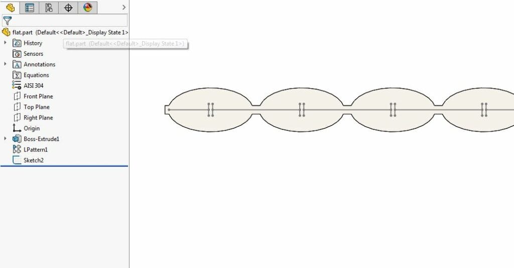
The issue we run into when saving this as a .dxf is that there is no option to specify different colors for different features.
As you can see in the preview window, the outline of the part and the sketch are the same color.
Sheet Metal Magic
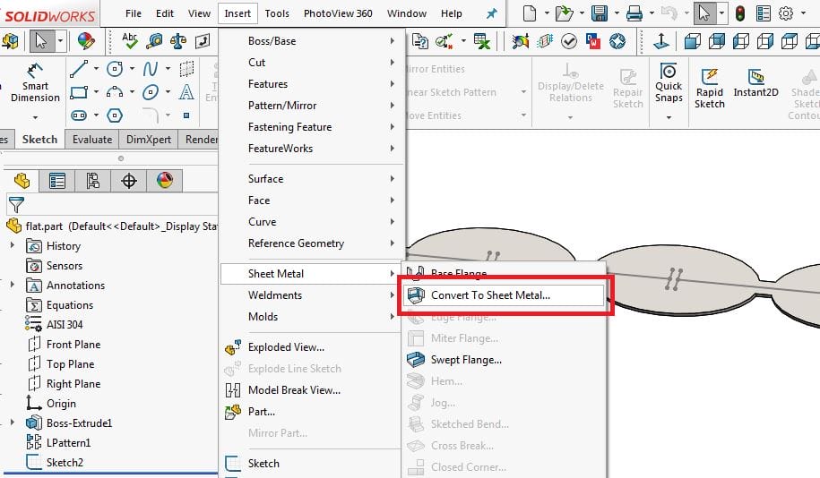
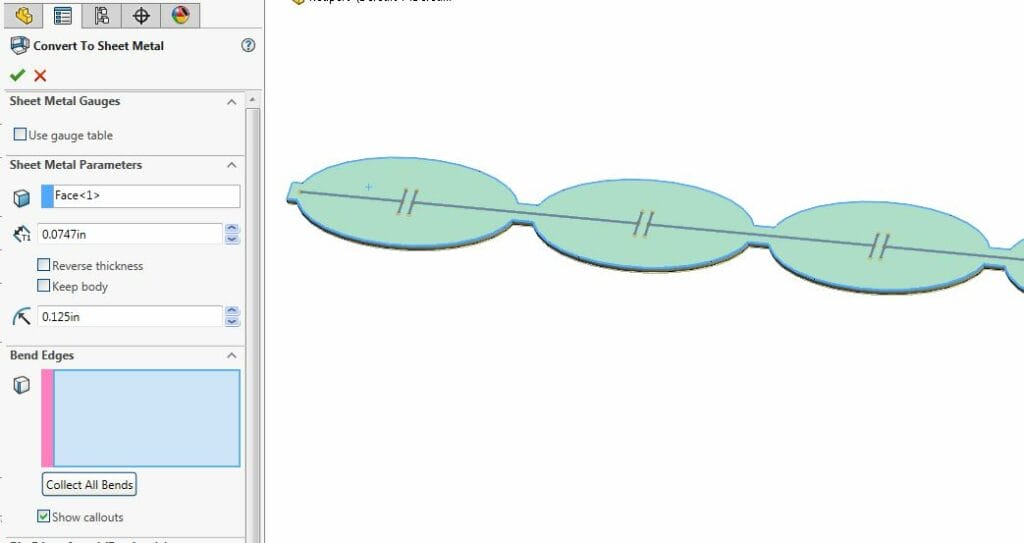
To fix this, we can simply convert this part to sheet metal. Select “Insert > Sheet Metal > Convert to Sheet Metal”
Next select the top face, and your desired metal thickness or gauge.
At this point, if you were to jump ahead and save this as a .dxf, you’d realize that the no-kerf sketch is still the same color as the part outline. To fix this we need to do a little property edit.
Fix System Options
System options can be overwhelming in a program like SolidWorks, but in this case, it’s super simple: In the “Save As” dialog, select .dxf and hit the “Options” button. Finally, check “Enable” in “Custom Map SOLIDWORKS to DXF/DWG.”
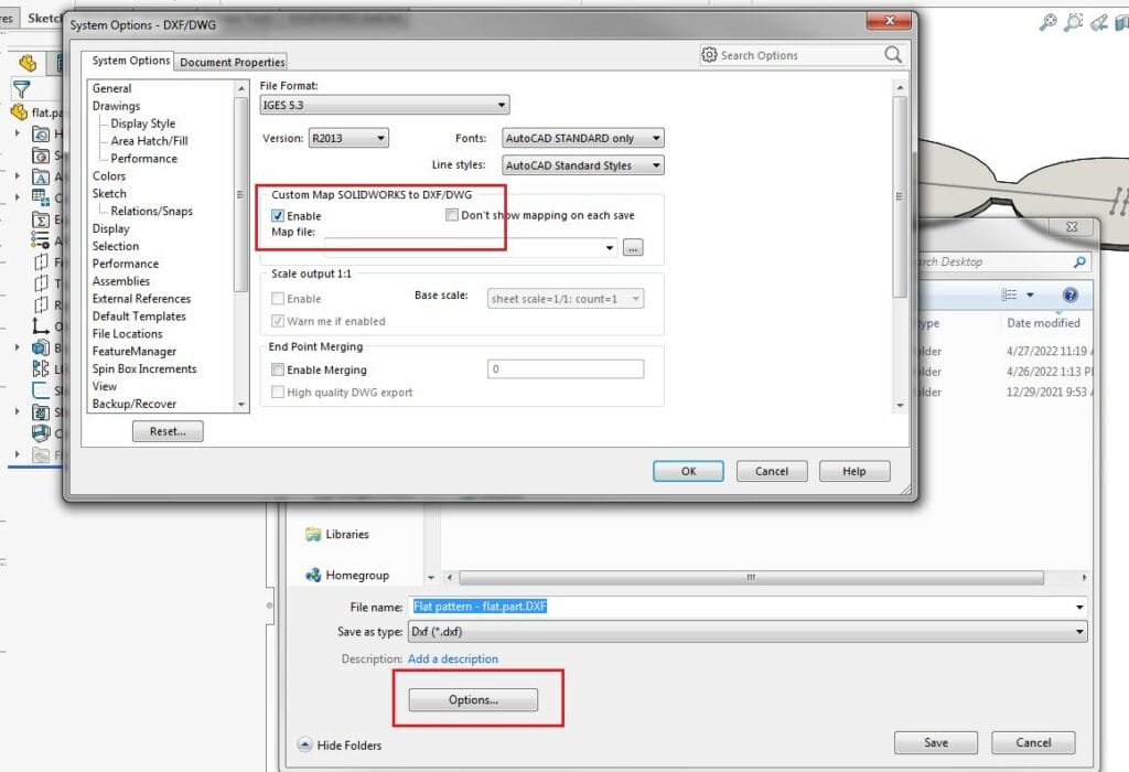
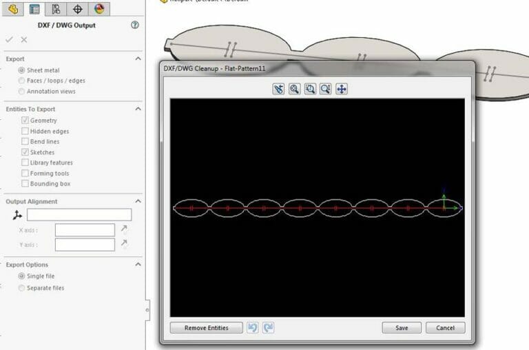
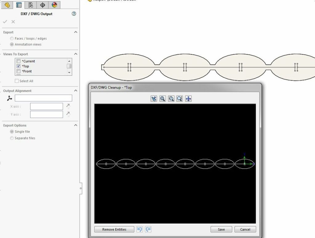
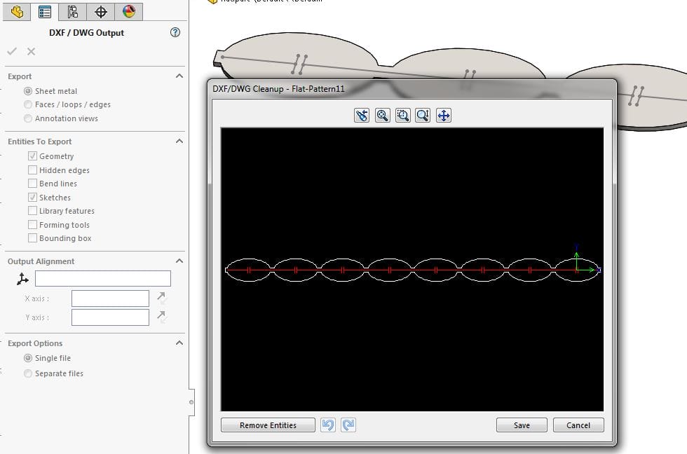
Now when you click “Save” you get a fancy new dialog box that allows you to map which features export into .dxf and also allows you to change their color properties individually.
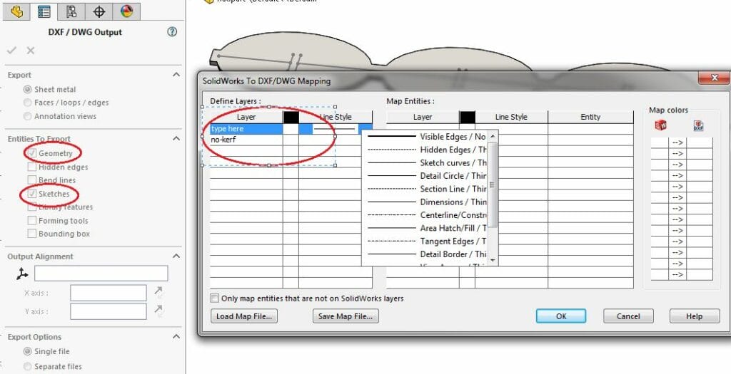
Note: Make sure you select both “Geometry” (the default) and “Sketches” in the “Entities To Export” options within the .dxf Output dialog.
Define and Export
You’ll notice that each cell under the “Define” and “Map” headings can be edited either by directly typing, or selecting from a drop-down menu.
Under “Define Layers” name the layers to differentiate the no-kerf geometry from your main outline and any closed-curve cuts by using “SCS_NOKERF” to name the sketch.
Tip: if you need single line etching instead of no kerf cuts, simply name the layer SCS_SLE instead.
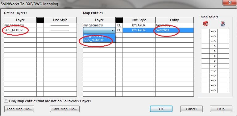
Under the “Layer” column in “Map Entities” you can select your newly-defined layer designations. Then move to the “Entity” column and select the Geometry and Sketches to match.
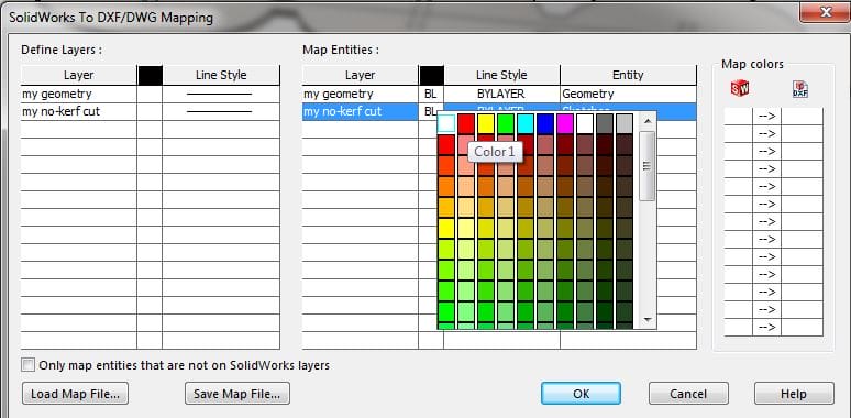
Select the color you like, and hit OK. In the cleanup preview, you’ll see the geometry in white, and the sketch in your color of choice. Save it where you can find it.
You are now free to upload the newly-colored .dxf file to the SendCutSend instant pricing tool!
Don’t be alarmed that the part preview doesn’t show the color you went through all that work to apply as the preview is in greyscale.
Leave an Order Note
The last step is to let us know that some of your parts have no-kerf cuts.
At the Address & Billing step of checkout, please leave an order note that specifies which of your designs include no-kerf geometry.
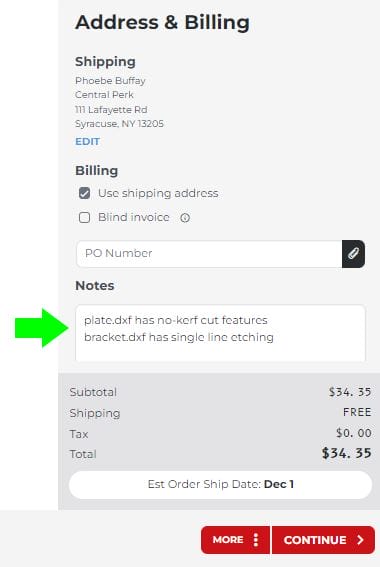
This will notify our team so they can review your design and ensure the file is good to go!
Try our SolidWorks Plugin
Before you begin, check out our SolidWorks Plugin. You can upload to SendCutSend and get live quotes without ever leaving SolidWorks.
“DXF” stands for “drawing exchange format.” This file type was created by Autodesk in an attempt to make a universal language for file types across multiple CAD programs. Before the use of .dxf files, every CAD program had a different default or preferred file type that wasn’t always accepted by other CAD programs. Now, although many CAD programs default to other file types still, .dxf files are pretty much universally recognized by any software.
A .dxf file can be used for just about anything and is used in dozens of industries. .Dxf is used for both 2D drawings and 3D files, with universal applications across dozens of CAD software. Used in large-scale engineering, architecture, and even for Cricut users, .dxf is one of the most universally accepted vector-based file types.
“DWG” is just an abbreviation for the word “drawing.” Like a .dxf file, it contains both 2D and 3D vector graphics. The key difference between the two is that .dwg utilizes binary code while .dxf utilizes text-based code. Binary code is more compact and efficient than text-based code, making .dwg files smaller relative to .dxf files.
“STL” stands for stereolithography, a technology used in 3D printing to help create 3D models and store 3D information. While .dxf can store both 2D and 3D information, a .stl can only be used for 3D models. This means that a .stl file is not vector based and thus cannot scale without losing quality.
