Here at SendCutSend, we have a few special services available for eligible laser cut materials – single line etching (this is not engraving), and single line “no kerf” through cutting (i.e., no kerf compensation).
In this guide, we’ll explain the characteristics and limitations of these services and how to set up your 2D vector file before placing an order. This will help your parts move into our production queue more smoothly.
Designs with single line etching or no kerf cut features cannot receive finishing services.
Note for Illustrator and Inkscape users
Preliminary setup for these services is only possible in CAD programs. If you’re designing in Adobe Illustrator or Inkscape, you can follow the steps in this guide but please leave a note before checkout indicating that parts in your order are in need of etching or no kerf cut features. SendCutSend’s Support team will get your note and ensure the files are set up correctly for production!
However, we strongly recommend designing parts that require these special services in CAD programs such as AutoCAD, SolidWorks, or QCAD.
If you use Autodesk Fusion to design your sheet metal parts, we recommend exporting a DXF format file of your design and opening the DXF in a program like AutoCAD or QCAD to add your single line etch geometry layer per this guide. QCAD is an open source software available to download for free.
Services
Single Line Etching
Single line etching is a service we can provide upon request for parts in the following laser cut materials:
- Aluminum (2024 T3, 5052, 6061, and 7075)
- 1075 Blue Temper Spring Steel
- 4130 Chromoly Steel
- Mild Steel (A36 / 1008)
- G90 Galvanized Steel
- Stainless Steel (304, 316)
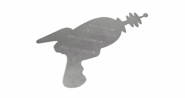
Please note, single line etching has a faint appearance that is best suited for part numbers and crosshair markings, not cosmetic applications.
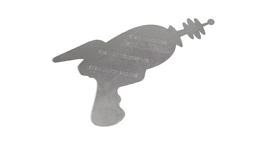
Also, if we etch a part, we won’t be able to deburr it since deburring will erase the faint etch.
We have more information and examples of what to expect here: Single Line Etching – SendCutSend
Single Line “No Kerf” Through-Cuts
We can provide “no kerf” cut features upon request in any laser cut material.
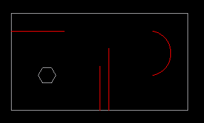
A single line “no kerf” through-cut refers to open cut geometry that will be the width of the laser’s cut path, because it does not form a closed shape.
Because the shape is not closed, there will be no kerf compensation for the cut, hence the name “no kerf” cut.
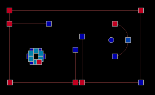
In the example below, the red paths are no kerf cuts.
Learn more about kerf and kerf compensation.
Pierce Points & Width
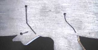
For single line no kerf cuts, there will be a visible pierce point where the laser begins the cut. In thinner materials the cut width is typically 0.008″ – 0.015″ wide, and the pierce point can be between 0.015″ – 0.030″ wide.
With thicker materials between 0.375″ – 0.500″ the cut width can be 0.015″-0.040″ wide with a pierce point between 0.030″ – 0.080″ wide.
Here is an example of typical pierce points:
Design Considerations
We cannot control where the laser will start each cut. If you order the same part more than once, the pierce point locations can be different each time.
We’ll need a node/anchor point to separate the paths where they intersect with normal cut geometry such as the part profile, like this:
These cuts will need to be the Min Bridge Size apart for the material and thickness chosen.
You can find the Min Bridge Size value for your material on the individual info page at our materials directory.
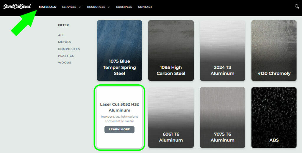
Once you’ve navigated to the specific material info page, scroll down to the Material Details section and click the desired stock thickness tab on the left.
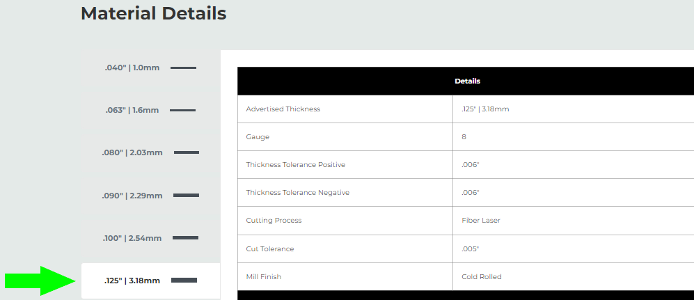
With the correct thickness selected, scroll down to the Design Considerations, where you’ll see Min Bridge Size. This value represents the smallest wall thickness or material left between cutouts that we can cut cleanly and reliably.
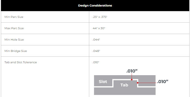
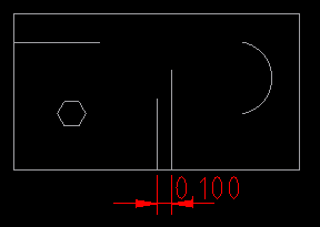
The dimension shown below is an example of a measured “bridge” thickness.
Setting Up Your Design
Essentially, you’ll need to move all normal cut paths onto one layer, and any etched or no-kerf paths onto a separate layer specifically named for the geometry required.
Then you’ll need to leave a note before checking out indicating which items are in need of special services.
Process
If your CAD program allows for layer creation and naming, you should be able to follow these steps. We also have a guide specifically for SolidWorks users who need to export a DXF with no-kerf cuts. You can follow the guide to set your file up for single line etching, too; just name the layer SCS_SLE instead of SCS_NOKERF.
If your CAD program does not allow for flexibility with layer creation and naming, we recommend QCAD since it is a free, well documented DXF editor. We have a thorough guide explaining how to download QCAD, set up your workspace, and learn some of QCAD’s most useful features.
Once you are set up with your CAD program of choice,
- Move all cut geometry to one layer and delete any superfluous layers
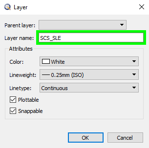
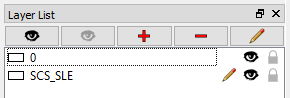
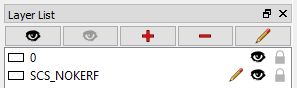
2. Create a separate layer named SCS_SLE or SCS_NOKERF.
If your design includes both types of geometry, create both additional layers.
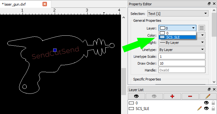
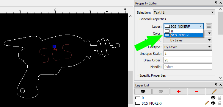
3. Move the paths to be etched or through-cut onto the SCS_SLE (single line etch) or SCS_NOKERF (through-cut) layer.
4. Any text or numbers will need to be exploded or expanded into paths if they are not already.
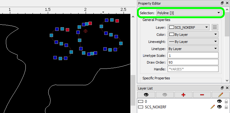
For example, in QCAD, you can select a text object with the cursor (keyboard shortcut QQ) and then press XP twice to explode the text and convert it to paths.
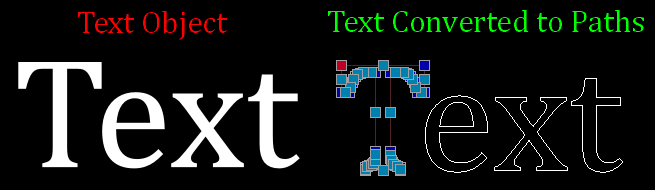
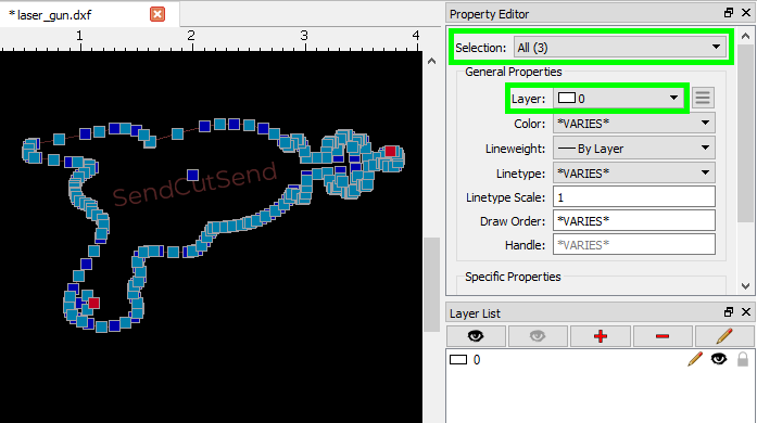
In QCAD, the Selection identifier in the Property Editor (GP) will also change from Text to Polyline.
5. Once your design file has the geometry separated into the appropriate layers, you can save it and upload your drawing to SendCutSend’s instant pricing tool.
Placing Your Order
Checking the Preview
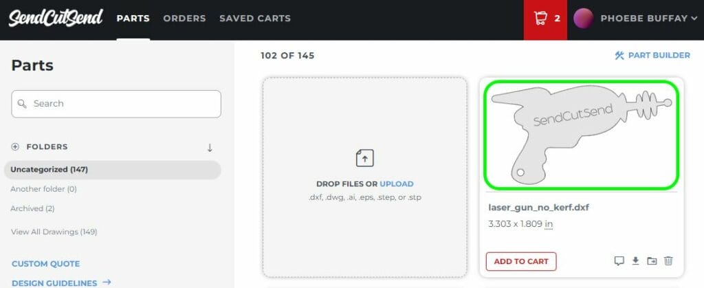
After uploading your files to our instant pricing tool or your SendCutSend account, you can check to see if your files are set up correctly by viewing the 2D preview of your parts.
You can take a closer look by clicking the preview image on each part.
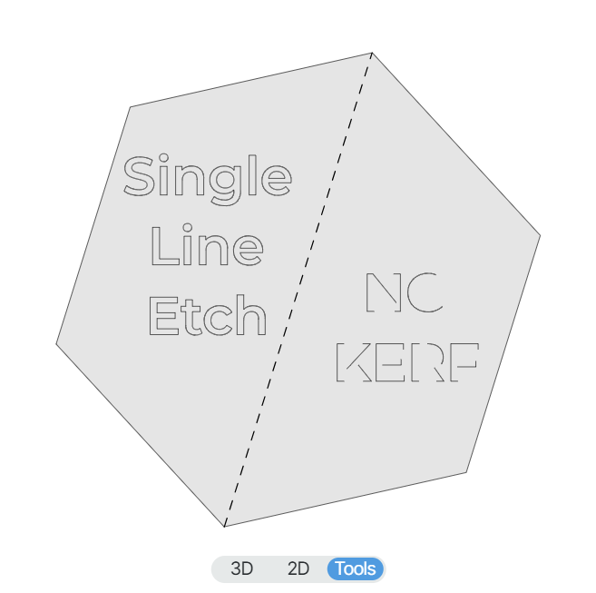
If your design with etching is set up correctly, any SLE (single line etch) geometry will show in the preview.
If you set the no kerf file up correctly, the geometry will preview as well.
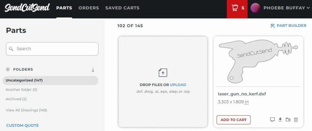
Add To Cart
For each design, click Add To Cart and choose your material and any additional services needed before proceeding to add the parts to your cart.
Leave an Order Note
Click View Cart to review your shopping cart and Address & Billing information.
Leave an order note indicating that which items are set up for single line etch and no-kerf cut services.
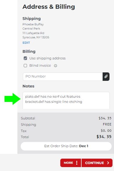
This will ensure that special attention is paid to your order. SendCutSend’s Support team will double check to make sure your files are set up correctly and receive the services you have requested.
Once you’ve added the note, you can proceed to the final steps and place your order! If there are any questions or concerns, the Support team will be in touch to ensure we have all the details correct.
A Fine Line
Whether you have a uniquely creative idea for no kerf cuts or need to differentiate identical parts in similar-looking materials with single line etching, these services can be great solutions to certain design problems. As soon as you’re ready to try single line geometry, upload your newest drawing to our website for a quote!
