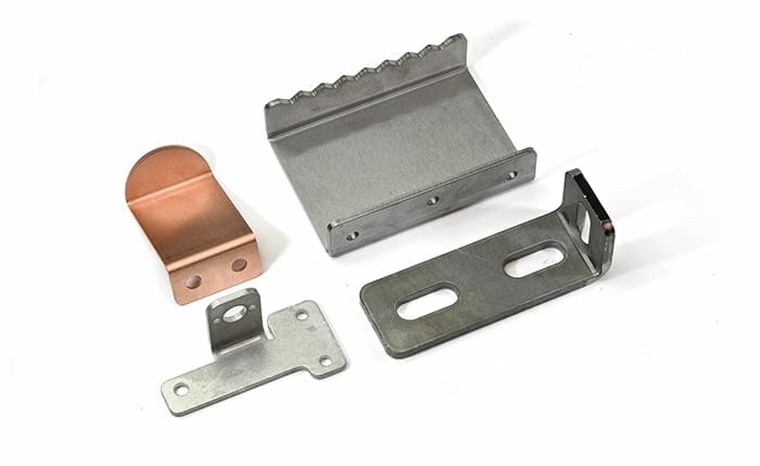
Precision sheet metal bending is one of our many high quality machining and manufacturing services here at SendCutSend. With some CNC magic, your 2D sheet metal part can transform into a 3D part in a matter of seconds. This is valuable for many applications: mounting brackets, suspension mounts, battery boxes, and other components that need to exist in more than two dimensions. It is known as one of the easiest ways to efficiently create a 3D part, and one of the best ways to minimize the number of individual parts in a design. Not so commonly known, however, is the structural benefit that bending often offers, and the reasons behind it: bending increases the design’s stiffness by a significant margin.
The Flexible Ruler
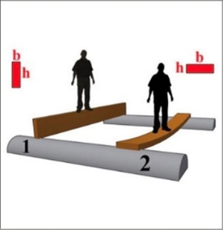
To understand where bending stiffness comes from, picture a simple deformable bridge, like a flexible ruler. Flexible rulers are easy to bend in one direction, and difficult to bend on their side. Is there some science behind this?
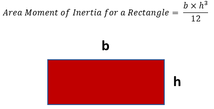
This phenomenon is due to something called “the area moment of inertia.” In layman’s terms, it is the resistance to bending due to the shape of the cross-section of an object. The higher the area moment of inertia, the stiffer the part.. For a rectangular cross-section shape, which applies to sheet metal, the area moment of inertia formula is:
Orientation Matters!
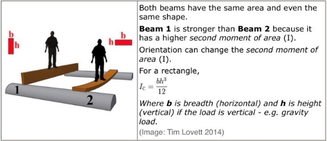
It is really important to know that the height – variable “h” – should always refer to the side of the cross-section that is in the same direction as the force causing the bending. The picture below shows this by making sure “h” is aligned vertically, because the person’s weight also acts vertically due to gravity.

Increasing “H” to Increase the Area Moment of Inertia
Another thing that is important to know is how to increase the area moment of inertia. In the picture below, both people are standing on a bridge that has the same rectangular cross-section, but the person on the left is standing on the stiffer bridge because it has a larger “h”. Go back and check the formula again for the area moment of inertia. The variable “h” is raised to the power of 3. That means that if you double (x2) the value of “h”, you octuple (x8) the area moment of inertia. In other words, if you double the height in the same direction of a bending load, you can actually make your part 8 times stiffer.
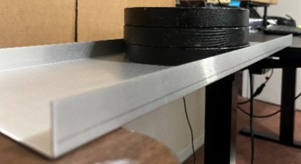
So what does this have to do with bending sheet metal? What if you had a long flat piece of sheet metal to serve as a shelf, and wanted to increase its stiffness? Going off the formula we just discussed, just increase “h” by bending the long edges 90 degrees.
Another good way of thinking about this is to create a flange that is parallel to the plane in which the bending will occur. It really is as simple as that. By bending you create flanges, and the flanges increase the area moment of inertia by increasing the geometrical height in the same direction as the bending load.
If the engineering theory has not convinced you yet, look at a simple experiment using two separate sheet metal parts:
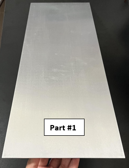
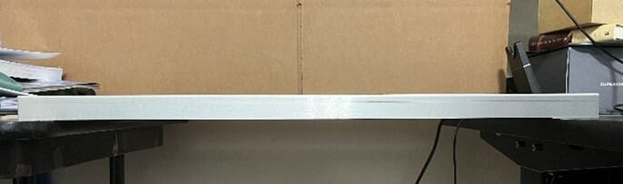
1. A long, flat 0.0625” thick aluminum sheet with no bends
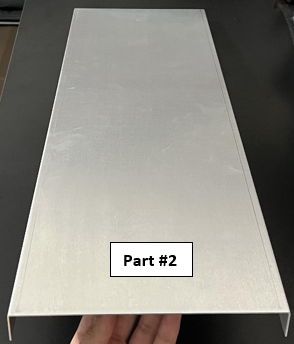
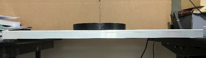
2. A long, flat 0.0625” thick aluminum sheet with the long edges bent 90 degrees
Both of them are the exact same length, width, and sheet thickness. However, the sheet with the bends has two flanges that are 1 inch in height. How do they behave as beams under heavy loads?
Bending Load Experiment
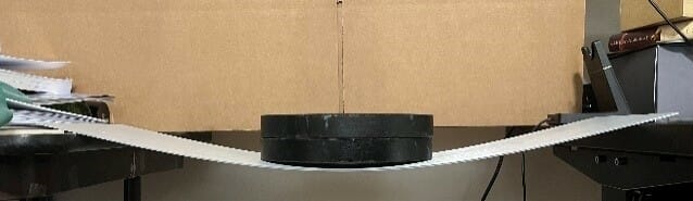
In the figures below, individual 7.5 lb weights were used to demonstrate the sheet metal resistance to bending under increased loading. Four loading cases were tested ranging from no-load to 22.5 lb.
On the left hand side, part #1 experiences obvious and large deflection under the loads. The increase in deflection can be clearly seen when comparing consecutive loading cases.
In contrast, the right hand side shows part #2 experiencing zero deflection even under the maximum load. When comparing the consecutive loading cases of part #2, there is no obvious difference from the no-load case. The simple bends of part #2 prove to increase the stiffness of the part by a significant amount. Again, this is due to the added geometrical height in the same direction as the bending load, as well as the bend flanges being parallel to the plane in which the bending occurs. This increases the area moment of inertia of the entire part and its resistance to bending.


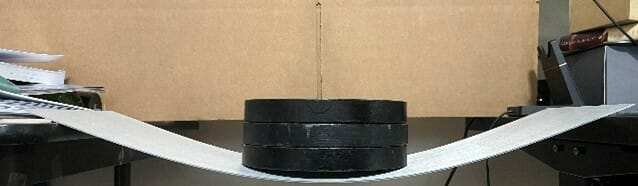


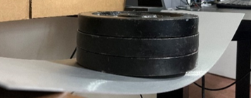
What if the bent part was flipped upside down? The following pictures show that as long as the height of the material is increased in the direction of the loading, the stiffness of the overall structure is greatly improved. Therefore it doesn’t matter if the bends in part #2 are up or down, because the increase in height is in the same direction as the force from the weights.
A real world example is that of an I-beam. It doesn’t matter if the “I” is upside down or not. Either way, the structure is designed to have height in the direction of the bending load.
Utilizing Bending Stiffness in Your Own Projects
Bending is a useful design implementation that can be beneficial for stiffening up structures, as well as adding strength to load-bearing parts and components undergoing bending loads. Exploiting the area moment of inertia is a wonderful engineering hack that enables this, while allowing for efficient uses of materials in order to save on material weight and cost.
Upload your part for a custom laser cutting and sheet metal bending quoting and see for yourself!


