11 Thicknesses
Production Time

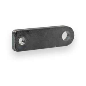
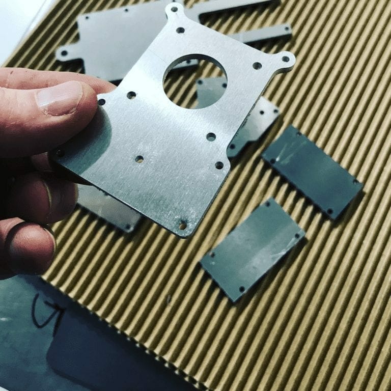
Laser cut, +/- .005" tolerance
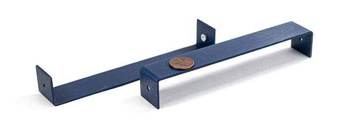
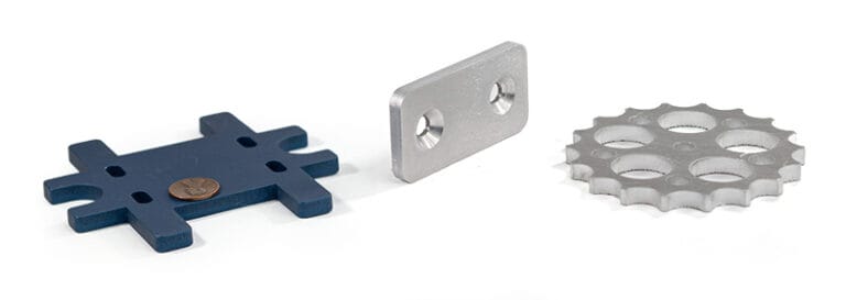
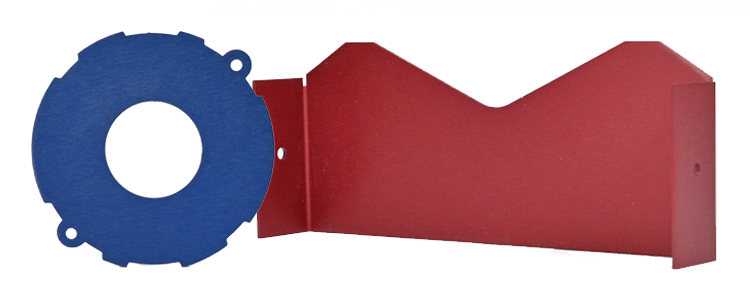
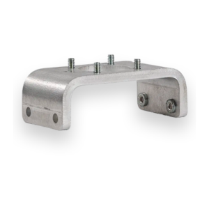
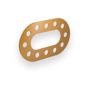
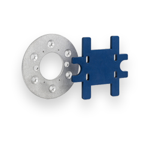
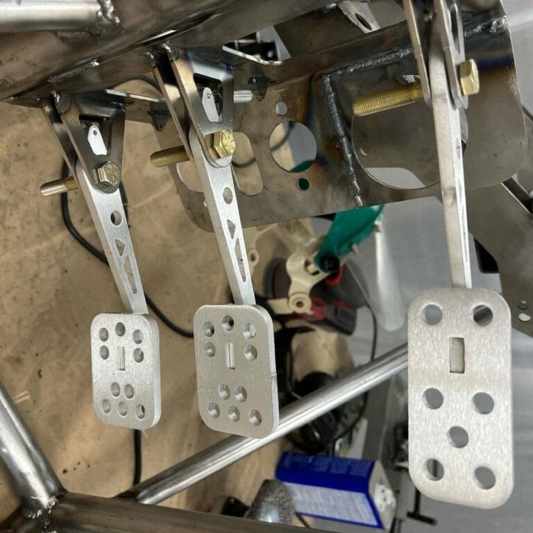
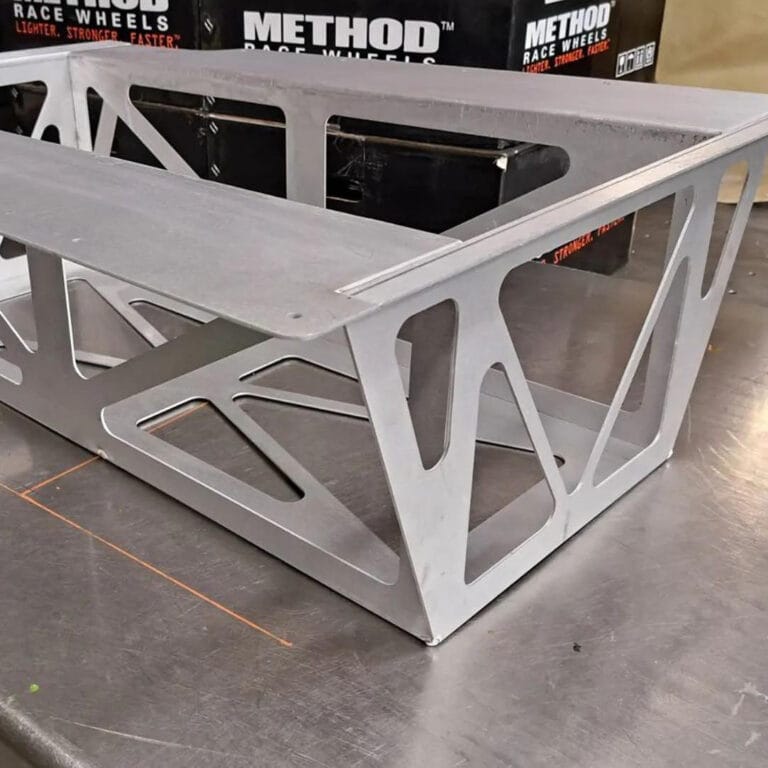
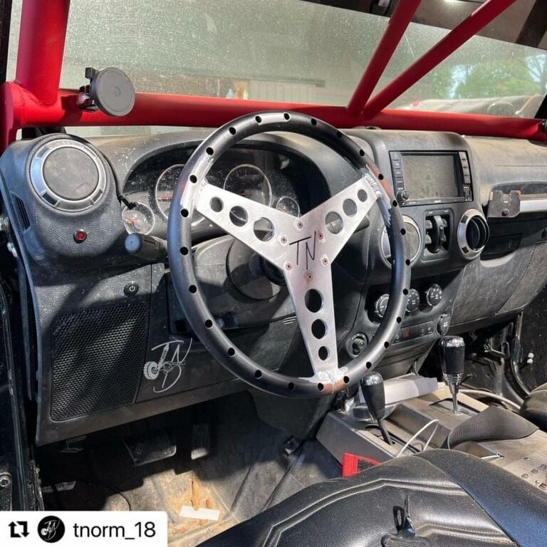
5052 H32 aluminum is strong, inexpensive, and lightweight. Whether you’re welding, machining, or bending, 5052 aluminum is going to be the go-to material for those projects that need excellent all-around material properties. Our laser cut 5052 aluminum is exceptionally lightweight and strong, making it perfect for projects where overall load is a concern.
With high relative ultimate strength (and fatigue strength), 5052 aluminum has a number of practical usages. It is non-heat treatable, which means that it is cold-worked to achieve its moderate-to-high strength properties. For greater strength, check out our 6061 series aluminum.
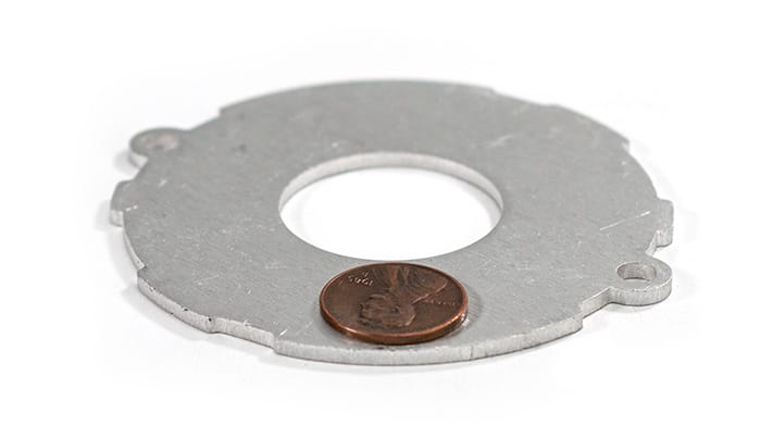
We source this high-demand metal through trustworthy suppliers with verifiable industry credentials so you don’t have to worry about it. You’ll know that our 5052 aluminum sheets are ready to be transformed into your greatest ideas.
Material certifications (PDF) are available below.
5052 Aluminum .040″
5052 Aluminun .063″
5052 Aluminum .080″
5052 Aluminum .100″
5052 Aluminum .125″
5052 Aluminum .190″
5052 Aluminum .250″
5052 Aluminum .375″
5052 Aluminum .500″
We guarantee awesome quality parts. If you’re not 100% happy, we’ll give you a refund or remake on the spot – no questions, no hassle.
SendCutSend offers 5052 H32 Aluminum in ten thickness options: .040″ (1.02mm), .063″ (1.60mm), .080″ (2.03mm), .090″ (2.29mm), .100″ (2.54mm), .125″ (3.18mm), .187″ (4.75mm), .250″ (6.35mm), .375″(9.5mm), .500″ (12.7mm).
5052 H32 Aluminum is available at SendCutSend with a range of thicknesses and part sizes. Instant quotes are possible for dimensions between .25″ x .375″ and 30″ x 44″, while custom quoting extends the maximum size to 30″ x 56″.
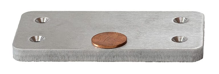
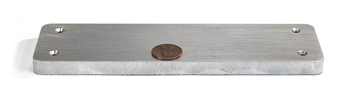
You can add the following services to your 5052 H32 Aluminum parts: Anodizing, Bending, Deburring, Countersinking, Deburring, Engraving, Dimple Forming, Hardware Insertion, Powder Coating, Tapping, Tumbling, and Welding
We accept .ai, .dxf, .dwg, .eps, .stp, and .step
Customize one of our simple parts templates

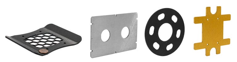
5052 aluminum is one of the most versatile and widely used aluminum alloys in fabrication. At SendCutSend, it’s also our most popular aluminum sheet metal option. Designers choose it because of its excellent corrosion resistance, good workability, and reliable strength for a wide range of projects.
Below you’ll find a comprehensive guide to 5052 aluminum—covering its properties, fabrication characteristics, and the most common questions customers ask before designing their parts.
When you’re selecting a material, understanding its mechanical properties is critical.
These properties make 5052 aluminum strong enough for enclosures, brackets, and automotive parts, but still formable enough for complex bends. Compared to 6061, it’s slightly weaker but much more forgiving to bend and shape.
No. Unlike alloys such as 6061, 5052 is not heat-treatable. Its strength comes from strain hardening (cold working) rather than heat treatment.
This is one of the most common comparisons. Here’s how 5052 stacks up against 6061:
In short:
One of the standout features of 5052 aluminum is its corrosion resistance, especially in marine environments. The magnesium in its chemistry provides excellent protection against saltwater and other aggressive environments.
Applications where 5052 is favored:
If your parts will see long-term outdoor use, 5052 is one of the best aluminum alloys available.
When it comes to sheet metal design, bendability is often the deciding factor between alloys. 5052 is among the most formable aluminums.
If you’re designing enclosures, brackets, or bent sheet parts, 5052 is an excellent option.
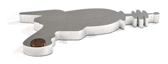
5052 aluminum cuts cleanly with high-powered industrial lasers. At SendCutSend, we cut 5052 up to .500″ thick with ±.005″ tolerance.
Edge quality:
5052 can be milled, drilled, and tapped, but machinists often call it “gummy.” It tends to:
For heavily machined components, 6061 is better. For laser-cut sheet metal parts, 5052 is the clear winner.
5052 aluminum is very weldable:
This makes 5052 a top choice for welded enclosures, automotive parts, and structural assemblies that need durability outdoors.
Designers often ask about minimum cut sizes and DFM rules for aluminum sheet.
At SendCutSend:
These rules reduce the risk of warping, cracking, or weak edges in your parts.
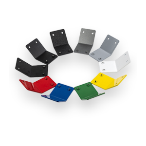
5052 takes surface finishes well, including:
At SendCutSend, powder coating is a popular choice for customers ordering 5052 parts. We also offer anodizing for 5052 aluminum.
Yes, 5052 aluminum is considered food-safe when properly finished. It’s often used in kitchen equipment, beverage cans (different alloyed temper), and food-handling enclosures.
For direct food-contact applications, a surface treatment like anodizing or powder coating is often applied for additional safety and durability.
How does 5052 behave in extreme conditions?
That makes 5052 reliable for outdoor and automotive use, but not suitable for high-heat applications near engines or exhaust systems.
When fabricating 5052 aluminum:
At SendCutSend, parts are cut and shipped ready-to-use, reducing risk for the end user.
You may wonder if you should cut 5052 aluminum yourself or outsource.
For professional-grade parts, outsourcing saves time and produces better results.
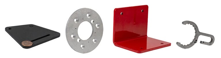
5052 aluminum strikes a balance that few other alloys can match. It’s strong enough for enclosures, panels, and brackets, but flexible enough to bend without cracking. It resists corrosion better than most aluminum alloys, making it a natural fit for marine and outdoor environments. And while it doesn’t machine quite as cleanly as 6061, its weldability and formability make it one of the most reliable sheet metals for laser cutting and fabrication.
At SendCutSend, we stock 5052 aluminum in 10 thicknesses from .040″ to .500″, cut it to a tight ±.005″ tolerance, and ship most orders in just 2–4 days. Whether you’re prototyping a custom bracket, building weather-resistant enclosures, or scaling up production parts, 5052 aluminum is a cost-effective, versatile choice that performs in the shop and in the field.