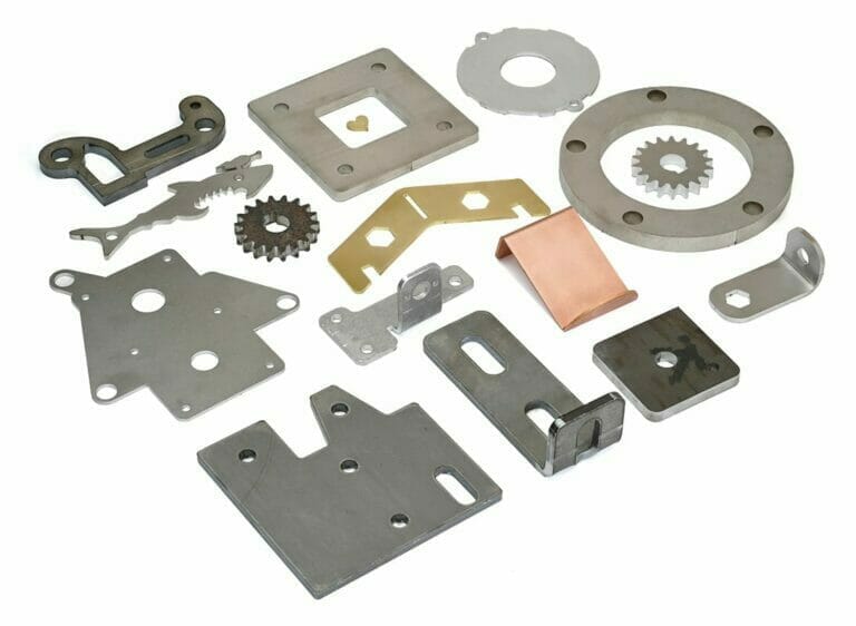
Nothing is worse than getting a shiny new part, installing it, and having it break immediately. We’ve all had that experience, so we’re going to show you how to prevent sheet metal part failure. We will be reviewing some of the most common ways parts fail, and some simple math you can do to ensure you can spend less time and money redesigning parts and more time enjoying them.
Sheet Metal Part Failure #1: Fastener Tearout
Fastener tearout refers to when a fastener rips through the side of a part. This is caused when there isn’t enough material to support the force being applied perpendicular to the length of the fastener, and the material fails, allowing the fastener to tear out the side. Remember notebook paper in a 3-ring binder, and how often one of those holes would rip through? Exactly the same thing, but with your painstakingly designed parts.
How to prevent fastener tearout
The general rule of thumb for fasteners is that measuring from the center of your bolt hole to the nearest material edge should be no less than 1.5x the nominal fastener outer diameter. For example: ¼-20 bolts have a nominal outer diameter of 1/4”, thus the closest it should be to any material edges is 1.5 x 0.25”= 0.375”. A similar rule of thumb applies between adjacent fastener holes. They should be at least 3x nominal fastener outer diameter between the bolt hole centers.
While rules of thumb are great, especially for thin or important parts, you might consider doing a simple bearing strength calculation. Bearing strength is how much force it would take before the material starts to fail. Don’t forget to include a factor of safety with these calculations. I.e. if your bearing strength is the same or close to your anticipated load, it’s probably not a good thing.
Bearing strength [lbf] = 1800 x Tensile Yield Strength [ksi]* x Hole Diameter [in] x Material Thickness [in]
*SendCutSend lists the Tensile Yield Strength of our materials in the Properties section of each material. Simply select the material you are interested in and scroll down to the Properties section to find this value.
Note: Anything in [brackets] in an equation is simply what unit that measurement or value should be in, i.e. should you input the length as feet or inches. Rules of thumb and calculations for fastener tearout are from AISC 360-16, a common structural engineering reference.
Sheet Metal Part Failure #2: Thread Pullout
Thread pullout is when a tapped part has the threads literally pulled out of the material. This happens when the force being applied along the length of a fastener is more than the threads can support, and the bolt rips the threads out of the part.
Picture what would happen if you threaded a screw through a piece of cardboard, and tried to support your body weight with it. That is the same way other, stronger materials can fail. This commonly happens when a fastener is overtightened, the material is too thin, the fastener is too small, or there aren’t enough fasteners for your intended use.
Overtightening a fastener is very common, and tearing out threads is a common result. To avoid this, consider using a torque wrench appropriate to your application, or some form of thread locking compound like Loctite to avoid the need to overtighten and prevent fasteners loosening over time.
How to prevent thread pullout
Proper thread engagement is needed in order to prevent thread pullout. Thread engagement is the length that the threads of the fastener are contacting the threads of the tapped part. Don’t forget to account for intermediate parts and/or washers when calculating thread engagement or necessary bolt length.
The general rule of thumb is thread engagement length needs to be at least 1-2x the nominal outer diameter of your fastener. Softer materials, such as plastics, copper, brass, and aluminum should have more thread engagement, such as 1.5-2x, while stronger materials like steel and stainless steel can have less thread engagement, such as 1-1.5x. Keep in mind, this is just a rule of thumb.
For especially important parts, directly calculate the thread failure strength. Don’t forget to include a factor of safety with these calculations. I.e. if your thread failure strength is the same or close to your anticipated load, it’s probably not a good thing. It is also generally preferred for the bolt to break before an internally threaded part. Bolts are cheap and easy to replace.
Thread Failure Strength [lbf] = 2350 x Material Shear Strength [ksi]* x Length Thread Engagement [in] x Fastener Nominal Diameter [in]
*SendCutSend lists the Material Shear Strength of our materials in the Properties section of each material. Simply select the material you are interested in and scroll down to the Properties section to find this value.
Note: Anything in [brackets] in an equation is simply what unit that measurement or value should be in, i.e. should you input the length as feet or inches. You can reference the thread failure strength equation in the NASA engineering library.
Sheet Metal Part Failure #3: Bending
Bending is exactly what it sounds like: a part deflecting (bending) into a new shape due to the applied forces. This generally becomes an issue when the bending becomes permanent damage to your part. Think of a paperclip. When you bend it slightly to go around papers, and it snaps back to its original shape, then you have bent the paperclip without damaging it, which is called elastic deformation. It snaps back into place like elastic does. However if you bend one of the legs out straight, it stays in that shape, and damages the paperclip. This damage is called plastic deformation, and it happens when the forces on your part create more stress than the Tensile Yield Strength of your part.
How to prevent bending?
Unlike the previous failure modes mentioned, calculating bending stress is a little more involved. Below I will present four of the most common ways forces are applied to sheet metal parts, and a simple version of their relevant equations for bending stress. Don’t forget to include a factor of safety with these calculations. I.e. if your bending strength is the same or close to your anticipated load, it’s probably not a good thing.
It is entirely possible that your part might experience multiples of these four loading situations, in which case the bending stress could add together or possibly even subtract. The loads could also be non-uniform, or not perfectly perpendicular to the part. These are more complicated situations that you should take into consideration, but are too in depth for this article.
All of the equations below only apply to rectangular shapes under simple loading conditions.
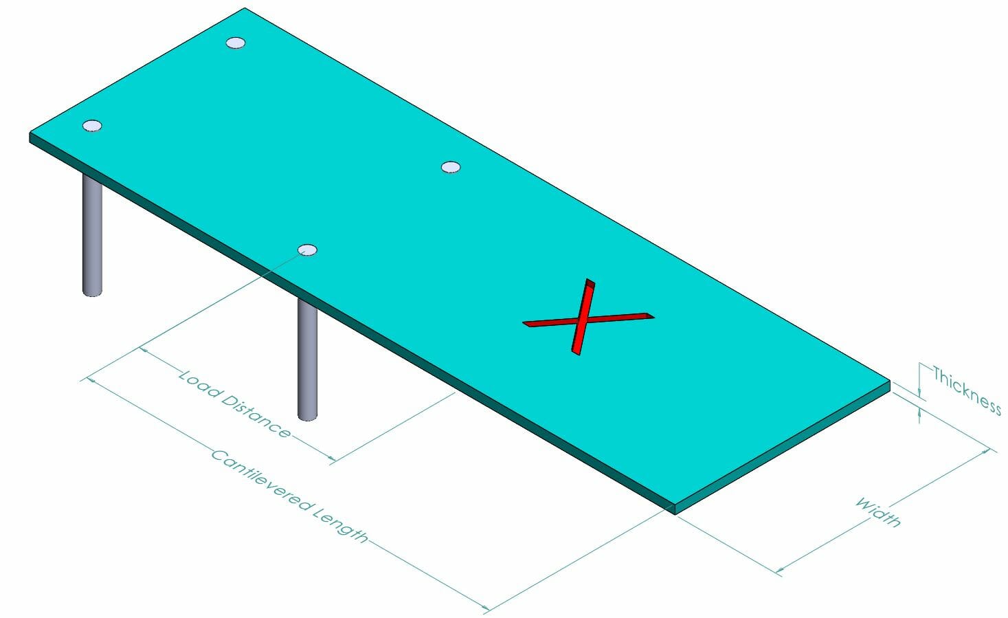
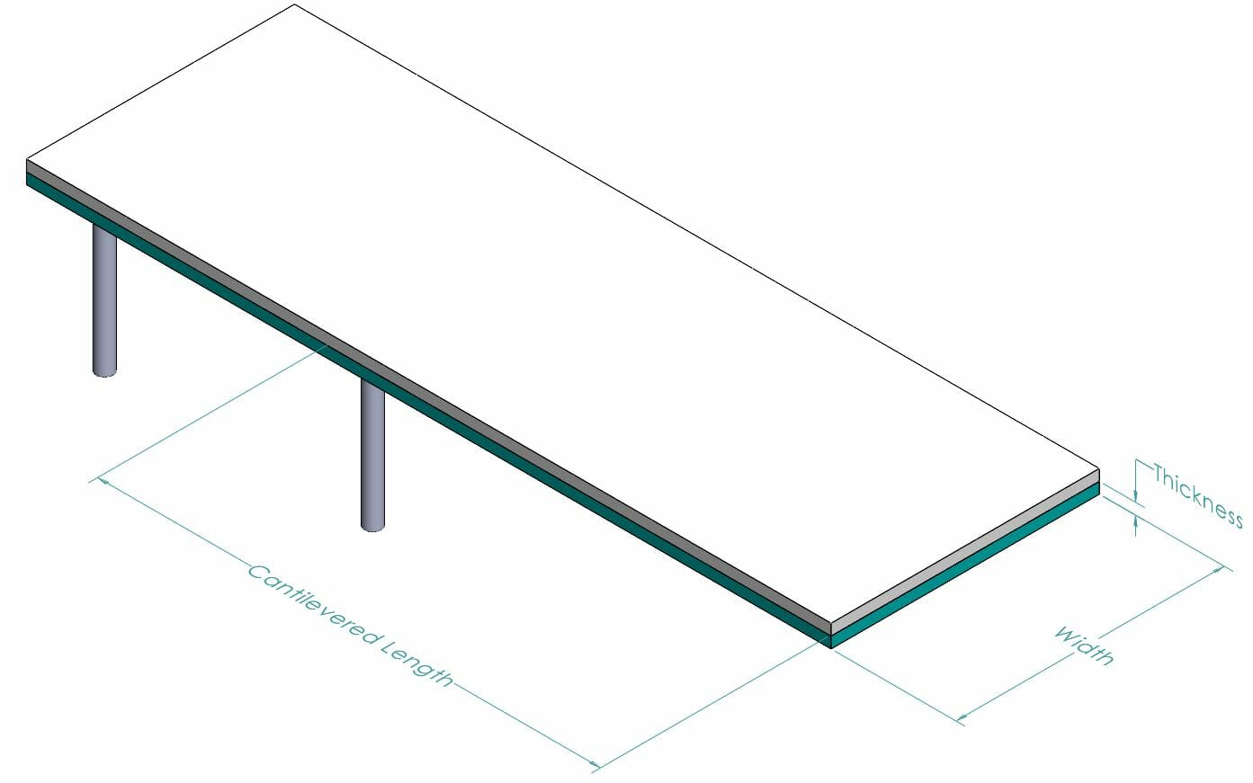
Cantilevered with Point Load
Think of a diving board with a diver at the flexible end about to jump off. The stiff end of the diving board is supported, but the other end is free to move around. The diver is a single force applied at a specific distance from the supported end. In the image below, the diver’s weight is being applied at the red x. Load distance is the length from the last support to the load application point.
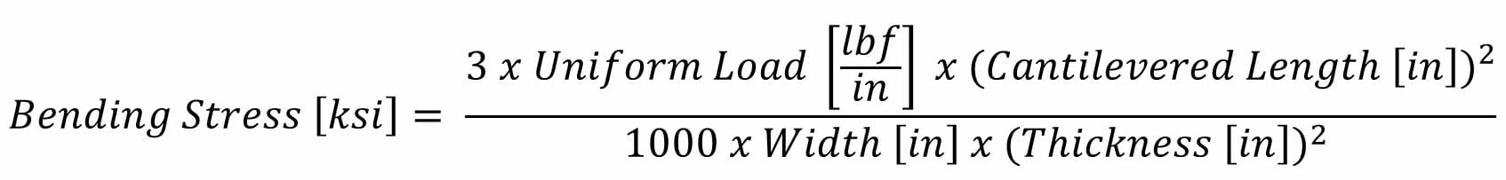
Cantilevered with Uniformly Distributed Load
Think of a diving board with an inch of snow on top of it. The stiff end of the diving board is supported, but the other end is free to move around. The snow is applying a uniform force across the entire diving board.
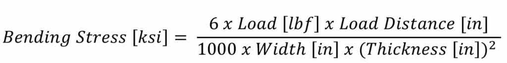
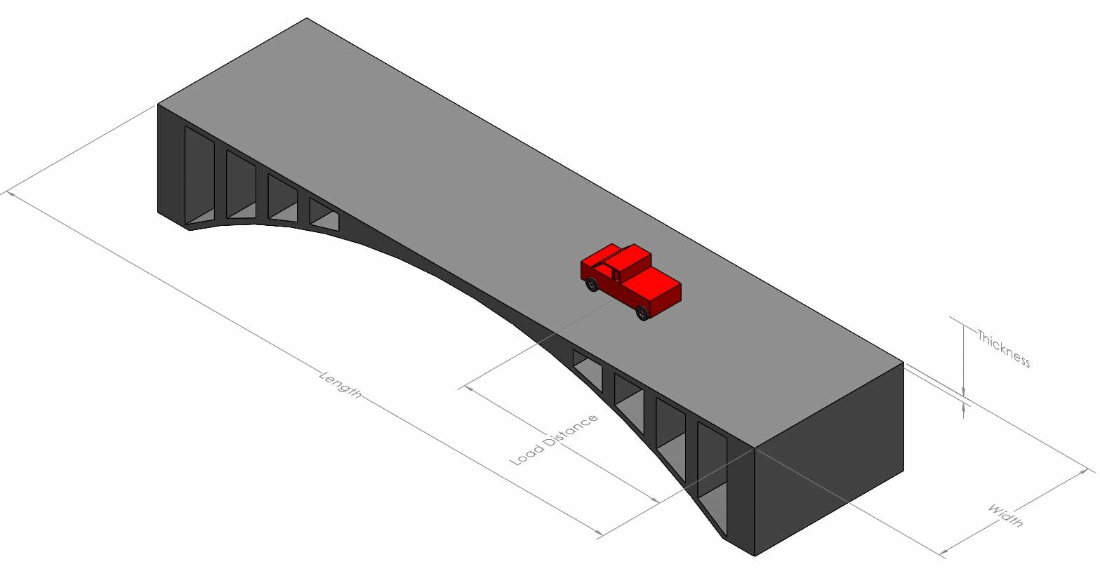
Fixed Supports with Point Load
Think of a bridge with a single vehicle on top of it. The bridge is supported on both ends, the vehicle is a single force applied at a specific distance from the ends. Load distance is the length from the support to the load application point.

Some terms abbreviated due to length of equation, outlined below:
L [in] = Length [in]
D [in] = Load Distance [in]
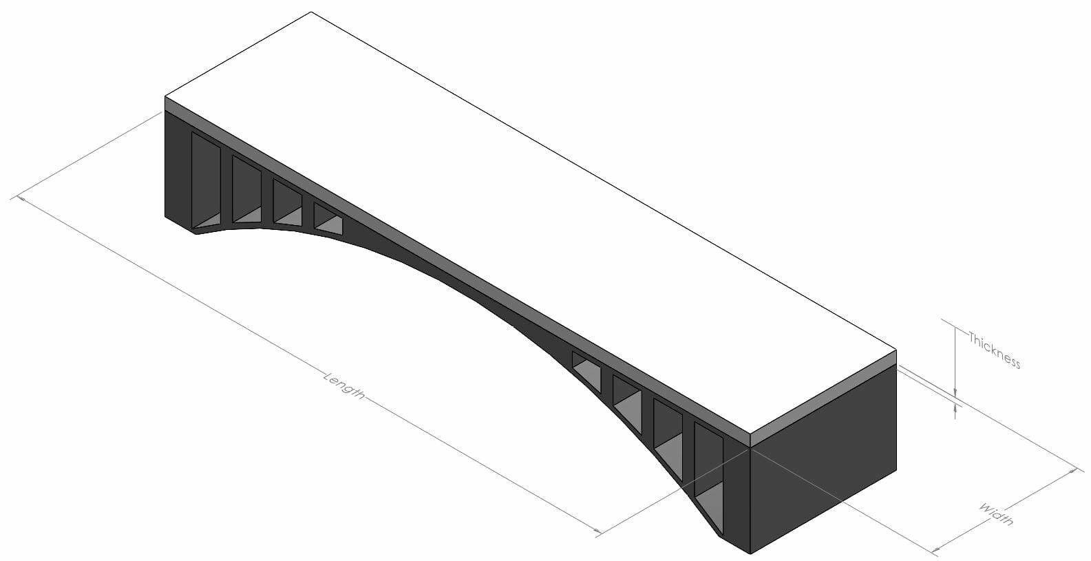
Fixed Supports with Uniformly Distributed Load
Think of a bridge with a foot of snow on top of it. The bridge is supported on both ends, and the snow is applying a uniform force across the entire bridge.

Sheet metal metal parts are a very cost and weight efficient way to accomplish many tasks. If you’ve made it this far in the article, then you should now be better prepared to design your parts to avoid many common sheet metal part failure modes. However if you have any questions, feel free to reach out to our support team.
When you’re ready, upload your design and get instant pricing today!


