If you’re cutting a sheet metal part that needs bends, your DXF or STEP file could get complicated. We offer quick and useful solutions in our parts builder that can help you build your part with the bending specifications you need. However, sometimes it’s easier to visualize and create the part in SolidWorks using their sheet metal design tools. If you’re interested in a more traditional method of designing sheet metal parts in SolidWorks, be sure to check out this article on designing for sheet metal bending.
However, if you find yourself deep in the trenches with some “fun” design work and the traditional methods are not working, consider the “Convert to Sheet Metal” tool demonstrated below. This tutorial will show you how to use this unique tool that is found in the sheet metal tab of SolidWorks.
Start with a CAD model
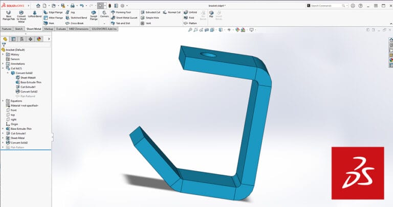
The benefits of this method for producing sheet metal designs in SolidWorks relies heavily on starting with a CAD model. Some geometries are easier to produce in SolidWorks using various extrusions, lofted bases, cuts, or chamfers. These geometries can represent the surfaces of a laser cut and formed sheet metal assembly. For example, the final design of a sheet metal part assembly might need to look like the basic model shown in the figure below.
This model can contain cutouts for mating parts, unique compound geometries, and multiple surfaces that might need to be created by implementing multiple sheet metal parts. This design approach also allows the designer to quickly change the base model and immediately implement those changes to multiple sheet metal parts. Let’s take a look at this magic in depth, shall we?
5 Steps to Using the Convert to Sheet Metal Tool in SolidWorks
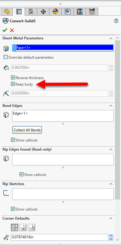
Step 1: Select the “Convert to Sheet Metal” tool from the sheet metal tab and select the first surface that will be considered as the “base flange”. Also, be sure to select the direction for the thickness of the sheet metal.
If you plan to create more sheet metal pieces from the 3D CAD model be sure to select “keep body” so you can use it again in a later step. If the intent is to only create one sheet metal piece from this body, then this option can be left unselected.
At this point it’s important to point out that basic sheet metal parameters must be applied to this design as well. This helps SolidWorks ensure that it calculates the appropriate flat pattern sizes to allow the final geometry to match your intentions.
Variables that you can adjust in SolidWorks such as bend radii, K-factors, and bend allowances / deductions all contribute to the final flat pattern dimensions. You can find plenty of information on bend radii and K-Factors in our other articles to determine which values to use for your material and designs.
Step 2: Once the sheet metal parameters are set, you can begin selecting the adjacent edges of the base flange where the sheet metal will be bent into a different plane than the base flange previously selected.
You may select as many bend edges as necessary, however, you’re limited by physics… so be sure that when the bends are unfolded, it results in a usable flat pattern. More on that is outlined in our sheet metal bending guidelines to ensure your part meets general service and material limitations. Also make sure the parameters adhere to our guidelines for things like minimum/maximum flange lengths, maximum bend angles and bending deformations.
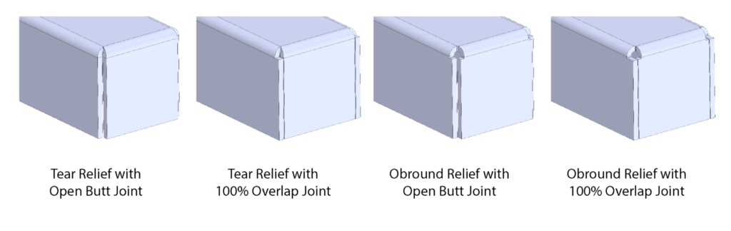
If the edges selected in this step result in a “box bend” where reliefs are required, be sure to select the appropriate settings here to ensure the desired joint. A few examples are shown and identified below.
Step 3: In Step 1, if you selected “keep body” the original body will remain along with the new sheet metal body. If necessary, you can create any other sheet metal parts to finish the assembly. This step is basically repeating Steps 1 and 2 in order to create another sheet metal body, see below for an example.
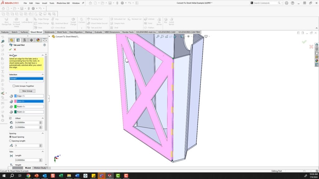
Step 4: At this point its easy to add any features such as corner radii to avoid sharp edges or tabs and slots to help assembly later on.
Step 5: Once you are happy with the overall design of the sheet metal part(s) the next step is to export the flat pattern(s). But, don’t forget to ensure that you have the correct sheet metal parameters for your material entered into the sheet metal parameters for SolidWorks.
In the feature tree, at the bottom you will see one or multiple flat patterns inside the flat pattern folder. Simply right click on the flat pattern that you want to export and “unsuppress” that pattern. Then you can right click on the face of the flat pattern and export the geometries and bend lines to a .DXF file.
Under “Export”, make sure “Sheet Metal” is selected and also choose “Geometry” and “Bend Lines”.
Using the Convert to Sheet Metal Tool in SolidWorks for Sheet Metal Bending Files
To recap, this tool requires some initial CAD body in SolidWorks with surfaces that will eventually represent the sheet metal surfaces/flanges.
Step 1: Select the tool and the base flange that is used to start forming adjacent flanges/bends
Step 2: Select edges on the CAD body adjacent to base flange that will locate bends in the sheet metal part. Close the dialogue when all bends are selected.
Step 3: Repeat steps 1 and 2 if multiple sheet metal parts are derived from single body.
Step 4: Add any features to sheet metal parts to assist in assembly or final design criteria
Step 5: Export flat pattern(s) using bending guidelines for processing with SendCutSend
As with any SolidWorks tool, you are generally limited by your own creativity once you master it, and that is truly the case with this tool. Try it out, and we look forward to seeing what you come up with!
Tip: If anything needs to be tweaked or changed in the overall size/shape of the assembly, you can adjust the original features/sketches that defined the CAD model that was used to “convert to sheet metal” and the changes will auto populate into the sheet metal parts as well as the associated flat patterns.
