Configuring bends on your bent sheet metal part within our app is easier than it might sound! Watch the video guide to learn how easy it is to go from CAD model to parts in hand.
Video Guide to Configuring Bends In Our App
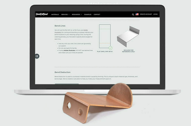
Important: set up your parts with SendCutSend’s bending specifications
Bending specifications like bend radius and K factor are set per material thickness and we do not offer custom bend radii at this time.
Be sure to design using our material bending specifications so your parts turn out as expected! You can confirm bending specifications in our Material Catalog or Bending Calculator.
- Using Autodesk Fusion or SolidWorks? Download our gauge tables to easily apply the right specs.
Taking a Bent Sheet Metal Part from CAD to the Real Thing
We strongly recommend using Autodesk Fusion to design your parts for manufacturing and bending with us. With a free hobbyist license and countless useful features available, it’s one of our most recommended software.
Bending in Autodesk Fusion is especially easy; you can export either a 2D .dxf file or save a 3D .step format file.
If you export a STEP/STP format file, ensure it meets our 3D file guidelines first. We have guidance on exporting 3D files from Fusion if needed!
To export a DXF format file, you can create a flat pattern from a 3D model with flanges by clicking one of the faces and selecting the Flat Pattern feature. This automatically opens up your pattern and lays it flat for cutting on a laser, waterjet, or CNC router. The Flat Pattern feature also gives you bend lines.
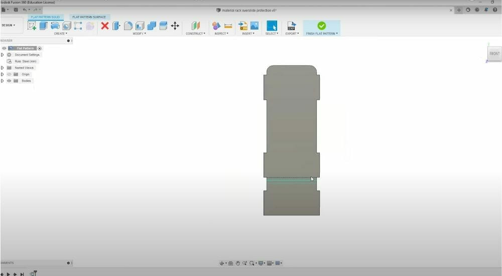
From this flat pattern, you can create a DXF and upload it to our website for instant quoting.
See which file types we recommend exporting from common design software.
Configuring Your Part In The SendCutSend App
Once you get the design files for your parts uploaded and you select your material, you’ll see the post-processing menu in our quoting process. Click on “Bending” to begin configuring bends in the app. For each bend, options will be located on the right side of the interactive menu.
You can adjust the angle to whatever your part requires as long as it falls within our bending guidelines. If you input an angle that is lower or higher than what is possible, it will autocorrect up or down to the minimum or maximum limit for the material thickness.
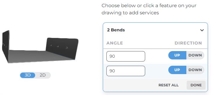
The next step is to select whether you want to place the bend “up” or “down.” It doesn’t matter on some parts, but remember you’re looking at the top flat face of the part in the viewer. “Up” would mean the flange is bent towards you and “down” would mean the flange is bent away from you. If the direction matters for your part, keep that orientation in mind so you can select the right position for your bends.
Once you’ve set your bend angles and selected the correct orientation, you’ll be able to view your part as a 3D model. Take this time to make sure that everything you’ve set during the checkout process is correct and aligns with the initial design you made in CAD. If needed, see our 3D preview troubleshooting guide.
Once you’ve checked the part in the 3D preview and finished your selection, click “Add Bending”. Then select “Add to Cart” and finish out your purchase. And you’re done configuring your bends in the SendCutSend app!
SendCutBendSend!
We’ve made it as simple as possible to design and order custom bent sheet metal parts online. You won’t have to wait days for a complicated quote or slow production times! Instead, you can see the estimated ship date for your parts at checkout and easily track your order through the production process.
If you have any questions about bending or our other services and processes, reach out to our support team. Ready to place your bent sheet metal part order? Upload your files and get instant pricing today!
