
*This article was updated on February 27, 2023
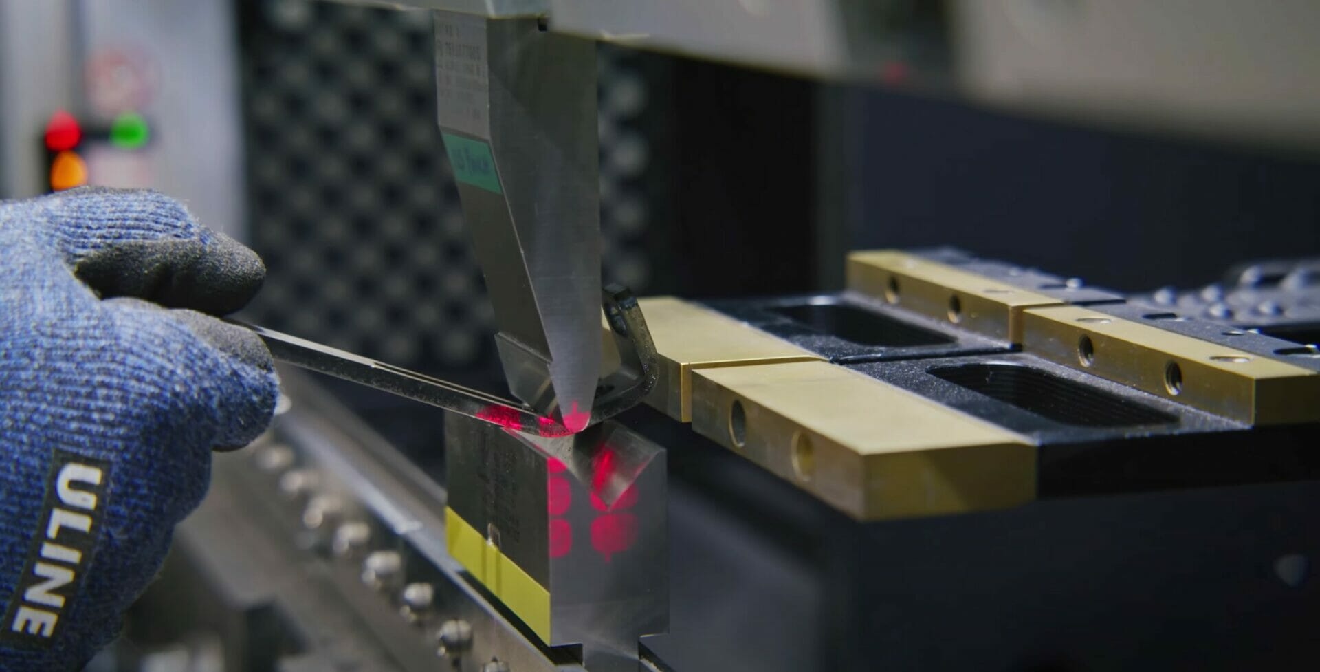
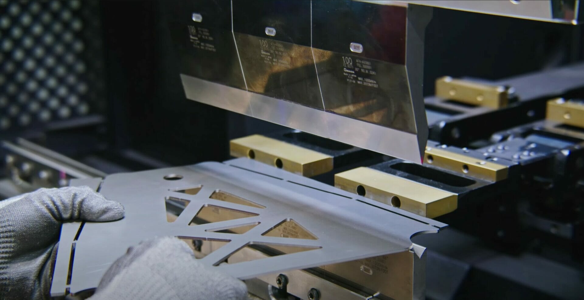
Our CNC bending service here at SendCutSend is affordable and accessible, making sheet metal bending available to everyone. There are a few guidelines you’ll need to follow to make sure that your bent sheet metal part is viable and successful. Watch the video and follow along with the guide below to help plan bends in your sheet metal parts.
Guide to Planning Sheet Metal Bends
Minimum Flange Length
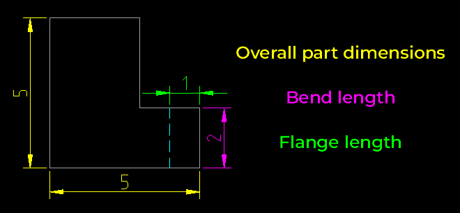
The first thing you need to know is the minimum flange length required for your specific part. But what is the “flange length?” Each bent part has a base flange and then the bent area. The flange length is going to be what’s measured off the tangent of the base flange, to the end of the bent area on the part.
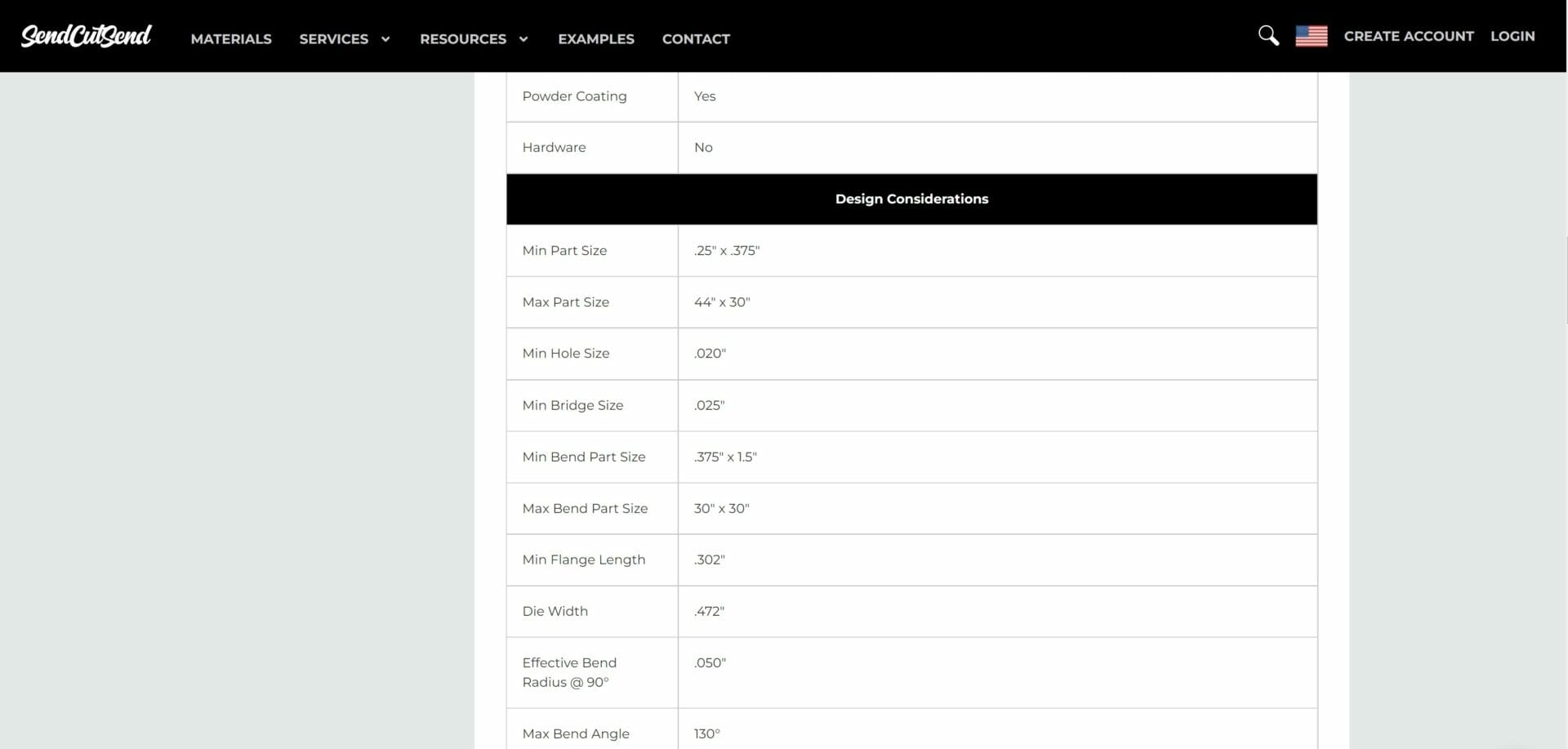
The best way to figure out the minimum flange length that you can have is to go to your chosen material’s page on our website and look at the design guidelines for that material and thickness. That’s going to tell you the minimum flange length for your specific part.
There, you can find both the Min Flange Length (Flat Pattern/Before Bend) and Min Flange Length (After Bend) under the Design Considerations. Use the Flat Pattern/Before Bend value if measuring on a flat pattern like the one shown above. If measuring your minimum flange length in a 3D program with the formed flange, use the After Bend minimum flange value.
Maximum Flat Dimension and Bend Length
The next limitation you need to be aware of is the maximum flat dimension. This references the max overall flat part size before bending. Looking at our Bending Guidelines page, you’ll see that the maximum flat dimension in most materials is 44” x 30”. What that means is that if you flatten out your part completely, the dimensions are no greater than 44 x 30 inches. This limitation is due to the tooling and physical size of our CNC brake.
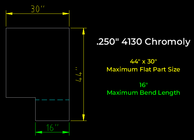
The maximum bend length is the maximum length of the bend itself. As an example, ¼” 4130 Chromoly has a maximum bend length of 16 inches. All other materials and thicknesses can be found in the Processing Min/Max chart.
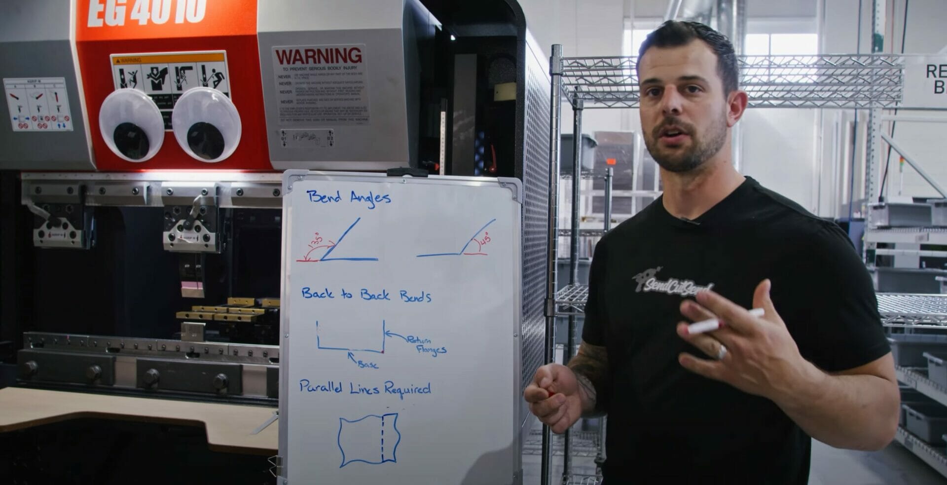
Measuring Bend Angles
It’s important to know how to measure bend angles in respect to putting them into the Bending Calculator and when uploading your files for quoting.
If you want your part to have a 45-degree, acute angle bend, you’ll need to measure it off the flat flange base and measure out 135-degrees. On the other hand, if you want the part to be an obtuse bend with a 135-degree included angle, you’ll measure off the flat edge at 45-degrees. If you’re putting this into the our bending calculator and want an acute angle, input 135-degrees. If you want an obtuse angle, you would input 45-degrees.
Max Return Flange Length and Designing U-Channel Bends
Another common situation is having a back-to-back bend such as a u-channel. The important thing to know about designing u-channel bends is the ratio between the base and the two return flanges. If you don’t leave enough space by having too long of a return flange, the tooling will contact the punch in the corner as the part is being bent.
A safe return flange to base flange ratio is 2:1 so as to prevent that contact. For example, if you have a base flange that is 2”, the maximum return flange lengths should be 1”.
Bending on a Non-Parallel Edge
The last note on planning bends is bending non-parallel edges. If you have a bend on a part that does not have any lines parallel to the bend line, you will need to add in a parallel edge. Our CNC brake has a back gauge that’s used to reference your part to make sure that the depth and angle of that bend is in the correct place. That gauge needs a parallel edge to reference for a successful bend.
You can add this edge by extending your design to include a flange that matches the contour of the non-parallel edge with a flat edge on the opposite side. You should then add in tabs to that flange that are the width of 50% the material thickness, with each tab spaced out by 1x the material thickness. Once you receive your parts, you can cut off those tabs and sand down what’s left, leaving you with a finished part bent with a non-parallel edge.
We have more advice on this subject here: Odd Flange Shape Guidelines

The Importance of Following the Bending Guidelines
Following these design considerations will get you well on your way to beautiful parts bent by our team here at SendCutSend, but what will ultimately ensure a successful bend is making sure your parts fit within the bending and manufacturing guidelines. This will also help us get your parts made and sent to you faster because you won’t need to adjust your designs after uploading them.
Once you’ve verified the parts against the guidelines, upload the files to our website and get instant pricing today!


