How to prevent bending deformation in sheet metal & plastic parts
To ensure your bent parts arrive distortion-free, please refer to the guidelines below.
Table of Contents
Tapered flanges
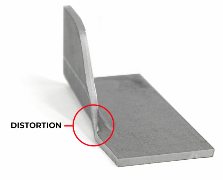
Every material we bend has a minimum flange length for bending. When flanges taper below the minimum, there is not sufficient contact on the tooling to execute force upon the material and form the tapered area. This causes the flange to distort.
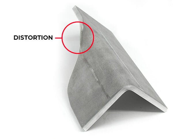
Additionally, in thicker and stronger materials like stainless steel and Chromoly, an asymmetrical flange can cause the part to “pull” during the bend operation since the bend is unevenly supported. This results in parts that are out of tolerance and can present a safety hazard for press brake operators.
Solution
To avoid distortion, you can add a relief along the bend line up to the point where the minimum flat flange length is met.
For more information please see Our Process: Air Bending. You can find the minimum flat flange length and minimum overall dimension for formed flanges on each individual material info page.
If a flange has an insufficient amount of material that meets the minimum flat flange requirement across the length of the bend, we will be unable to form the flange within our established tolerances. Bending the part as designed would result in significant deformation as seen here.
Solution (.187″ thickness or less)
To avoid distortion in areas that cannot bend, you can add reliefs as shown in the example below. You may refer to our Guide to Designing Bend Reliefs for more details.
Recommended Bend Relief Depth if measured from bend line: Effective Bend Radius + 0.020” Bend Relief Depth: 0.270”
Solution (.250″ thickness)
Approximately 50% of a bend’s length must meet the minimum flat flange length for the material to be formed successfully. If you receive an unsupported bend error for thicknesses greater than .187″, please increase the length of your flange across the bend.
Due to safety and tolerance considerations, materials 0.187” and thicker may require that the minimum flange length be met on both sides of the bend line for the full bend length.
You can find the minimum flat flange length (before bending) and minimum overall dimension (formed flange length) on each individual material info page.
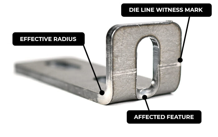
Die lines are the full extent of the width of the tooling, or die, that we use to form parts. When a part is bent, witness marks are left where the die makes contact with the part. These points of contact are what we refer to as die lines.
These points of contact (witness marks) are what we refer to as die lines
The problem: feature distortion
While the effective bend radius for our materials ranges from .024″ – .250″, the dies we use will span at least .472″ -1.575″ across the bend line. We cannot offer cosmetic protection along the die lines, so holes, edges, and other cutouts are subject to distorting in the bend process.
For example, a part cut from 0.104” mild steel will be bent with a 0.630” die. This means that any cut feature that is 0.315” or less away from the bend line (center of the bend) will be distorted in the forming process.
Large cutouts and other features in the die line may cause uneven pressure during the bending process. This may result in the bend line to shift and not be square.
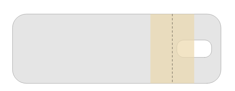
When ordering your part from us, we will show you the feature distortion caution area when you configure your bend angles. The hole in the yellow portion of this screenshot will be distorted.
You can measure the die width on your flat pattern prior to uploading your file. Reference the die width for your material from our material library. The center of your die with will fall on the bend line as shown in this example.
.104″ Mild Steel Die width: .630″
Solution
If features fall within the die line of our tooling, you should remove them or adjust their location. Check out each material page to see what die we will use for your material of choice, and make sure your cut features are at least half the die’s width away from the bend line.
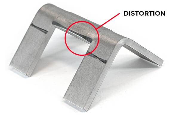
Ensure all holes and cutouts on your design fall outside of the die width area. In the examples below the holes on one side of the bend are in the distortion area, while the other is not.
Pre-flight checklist
File is in a format that we accept (2D: .dxf, .dwg, .ai, .eps; 3D: .step or .stp)
All holes and cutouts are at least 50% material thickness for laser cut parts
All holes and cutouts are no less than 0.070” for most waterjet cut parts
All holes and cutouts are no less than 0.125” for all CNC routed parts
File is built at a 1:1 scale, preferably in inch or mm units
2D files: all objects on the same layer, text converted to outlines, no open contours, all shapes united or merged, floating interiors bridged or stencilized
3D files: single solid sheet metal body, uniform thickness with a face at every edge, modeled at stock thickness with matching bend specs
All stray points, duplicate lines, empty objects and text areas have been removed
Additional Bending Resources
We have additional guidance about planning cut features around bend lines here, and a complete bending preflight checklist available here.
Upload your CAD design, or try one of our customizable part templates to get instant pricing on your custom laser cut parts. All delivered to your door in a matter of days.