Tabs and slots are great design features that allow for laser cut parts to fit together. They provide a simple way to have a design fixtured or set in place without the immediate need for adhesives or other fasteners. As a result, they are usually helpful for projects that involve welding or bolt assembly, in which the parts need to be held together before final assembly or welding.
When designing using tabs and slots, there are usually more than one tab and slot pair. This is the case in order to make the part connection more secure. The greater the number of tabs and slots, the more constrained the fixture becomes. As a result, it can be daunting to think of designing tabs and slots using CAD (Computer Aided Design) because of the large number of tabs and slots you might need to sketch and design using the software. Thankfully however, most CAD softwares have built-in features to quickly create several tabs and slots with the click of a few buttons.
SolidWorks is one of the most popular CAD softwares, and this article will outline how to use its tab and slot design feature to create a simple stand geometry.
Create Individual Parts
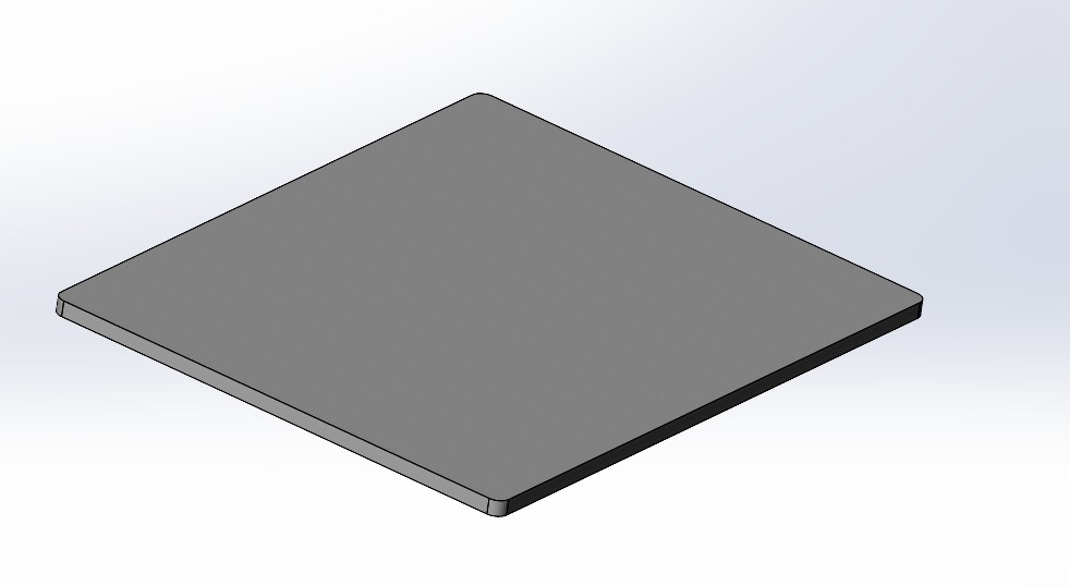
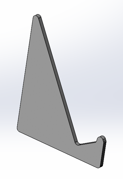
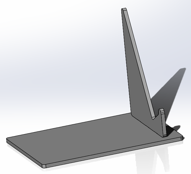
The tab and slot feature in SolidWorks requires a 3D part to already be created. For the purposes of this tutorial, the example geometries that will be used are in the figures below. Tabs and slots will be added to these base shapes so that they can be mated together perpendicularly after being laser cut out of sheet metal.
Check out the following articles if you need to review how to create simple sketches and parts in SolidWorks:
Create Assembly
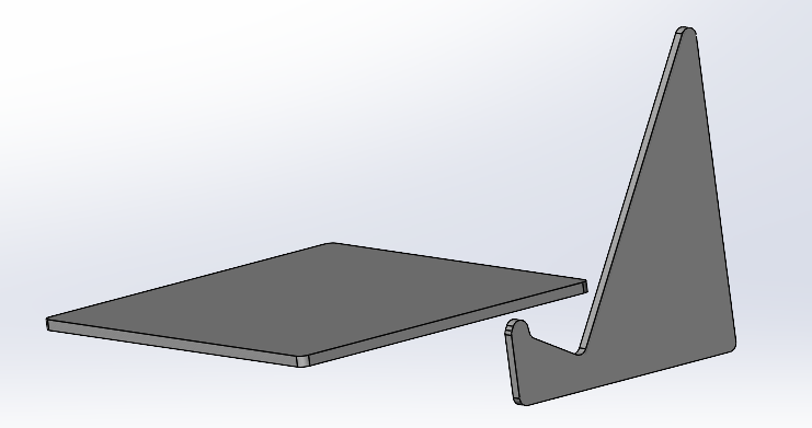
Before adding tabs and slots to your design, it is necessary to bring the two parts together in their intended positions.
To do this open an assembly file and click “Insert Components”. It will then give you the option to select the individual part files you want to have in this assembly. Select them and click ok. You will then be able to position each part in the 3D space. Do not worry about placing them perfectly with respect to each other at this point. The next step shows how to mate the parts together.

To mate the parts together, click on the “Mate” button next to the “Insert Components” button. The icon for the mate button is a paperclip figure.
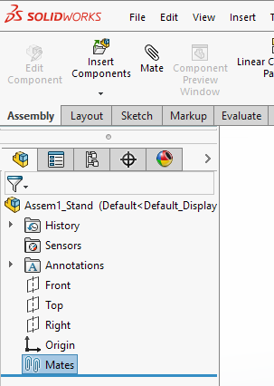
Once the mate button is selected, the model tree in the left gives several options that prescribe the mating/contact relationship between the individual parts.
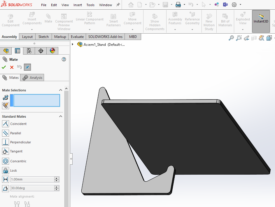
Select the surfaces that you want to mate together by utilizing the SHIFT button to select them at the same time.
The default mating type is “coincident”. Select the green check mark to complete the coincident placement.
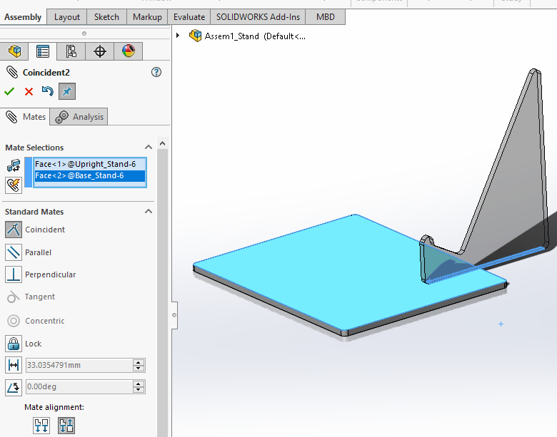
After the parts have been made coincident, more placement considerations can be made, such as prescribing distances between edges. The figure below shows the “distance” mating feature being applied to edges so that the vertical part is oriented properly with respect to the bottom plate. This can also be done again to orient the part with respect to other edges of the bottom plate.

Create Tabs and Slots
Once the parts are positioned correctly, the tab and slots can be made in the design. To do this, right click on the part that will have tabs, and select “Edit Part”.
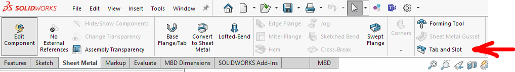
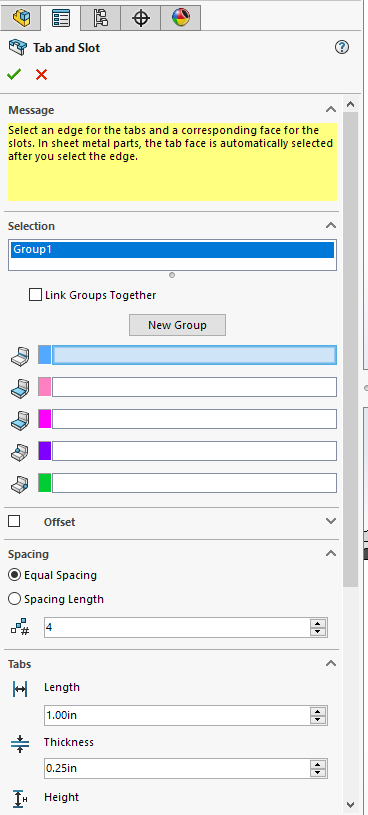
At the top of the screen, the ribbon that appears shows an option for “Tab and Slot” under the “Sheet Metal” tab. Select “Tab and Slot” and observe new design options that appear over the design tree at the left of the screen
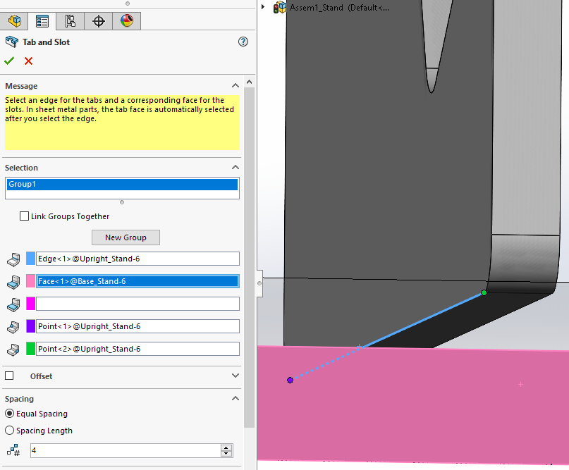
To place the tabs, start off by selecting the linear edge corresponding to where you want the tabs to be located. Then, select the face that will be on the opposite side of the slots. In the figure below, the edge is highlighted in blue, and the opposite slot face is highlighted in pink.
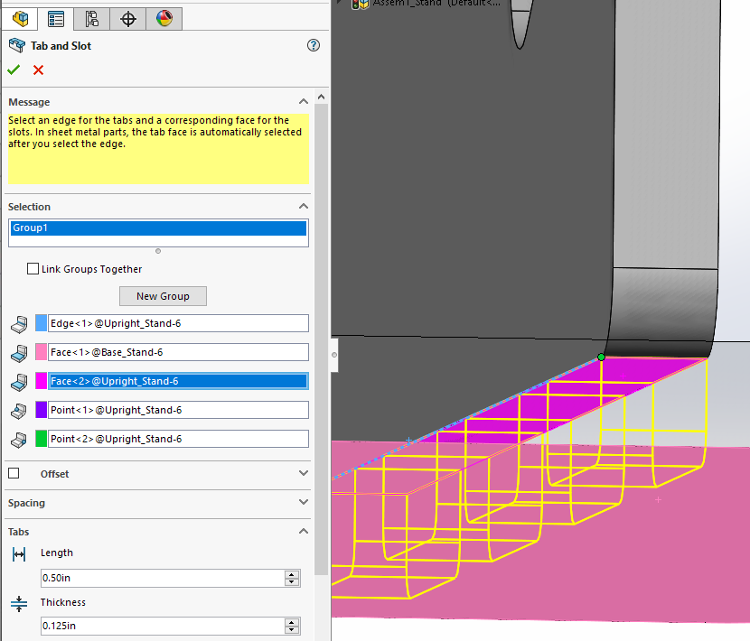
Finally, select a face that is shared by the selected edge, and that will serve as the face from which the tabs originate.
In the figure below, this face is highlighted in bright pink. SolidWorks will show a preview of the tab geometry, represented by yellow lines.
If you get an error, try changing the tab length and thickness parameters to values that make sense according to the thickness and size of the sheet metal in your CAD geometry.
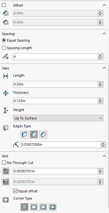
In addition to the tab length and thickness, other parameters available to change are offset, spacing, edge type, height, and a slot clearance option.
The figure below shows all the options available.
The offset option allows you to start the array of tabs a certain offset distance away from the start of the edge.
The spacing option prescribes the distance between each tab, or the number of tabs desired in the case of equal spacing.
Additionally, the height option prescribes the height of the tab, while the edge option allows for rounds, chamfers, or straight tab edges.
Finally, the last section of the option tree allows for prescribing clearance and different corner types for the slot hole around the tab. Refer to SendCutSend documentation for advice and best practices when it comes to designing tabs and slots.
Once you are content with the tab and slot design parameters, select the green check mark, and exit the “Edit Part” window. The assembly view returns, and the tab and slot features appear in the assembly design.
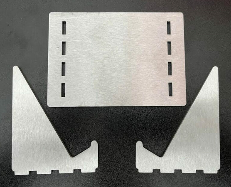
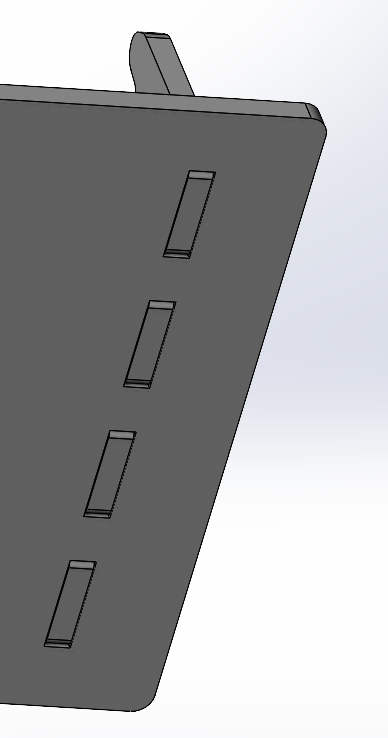
You can also mirror slots successfully by simply opening the base work part and mirroring the slots across a prescribed plane. The images below show the resulting geometry.
As mentioned before, tabs and slots are very useful when designing for parts that need to be fixtured. SolidWorks presents a very useful tabs and slots tool that allows for quick and easy designing.
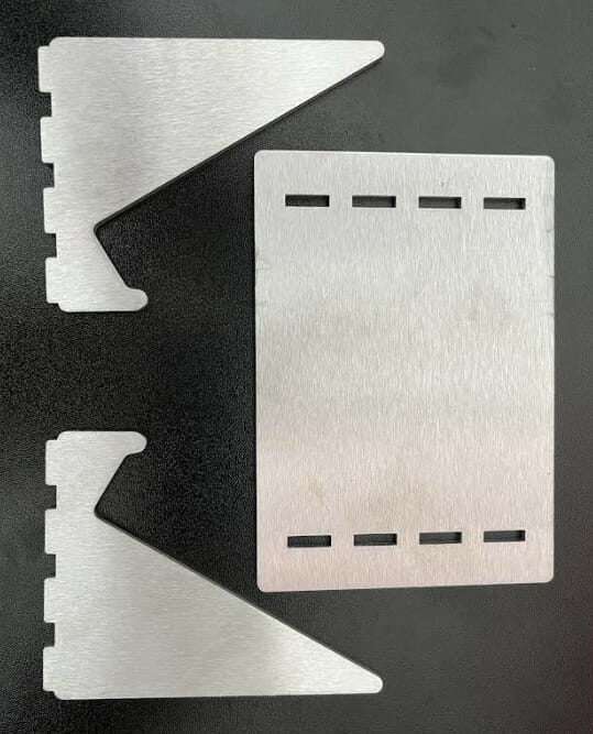
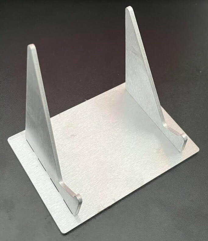
To prove the accuracy of the SolidWorks tabs and slot feature, parts were laser cut by SendCutSend and assembled using the designs from the figures above. The upright part was mirrored across the assembly to create a simple stand geometry. A geometry such as this allows for a self-fixturing structure that is useful when welding or other types of assembly is required.
If you want to create fixtured joints with tabs and slots using SolidWorks, review the steps in this article a few times and you will be a CAD tab and slot expert in no time!
SendCutSend provides low cost laser cutting services across the US. If you’re looking for laser cutting near me consider our online laser cutting services which provide fast turn-arounds and parts to your door in just a few days. If you have any questions feel free to explore our instant pricing tool and contact us.
For more CAD tutorials, check out our extensive list of SolidWorks tutorials.
Try our SolidWorks Plugin
If you are using SolidWorks 2021 or newer, check out our SolidWorks Plugin. You can upload to SendCutSend and get live quotes without ever leaving SolidWorks.
