This tutorial introduces SolidWorks and explains how to create a 2D sketch in SolidWorks. SolidWorks is an industry standard Computer Aided Design (CAD) software used in engineering and design. It uses parametric modeling to accomplish this.
This is the first part of a two-part series, “A Beginner’s Guide to SolidWorks.” The 2D sketch in this tutorial is transformed into a 3D part in the article, “Introduction to SolidWorks: Creating a 3D Part From a 2D Sketch.”
Before you begin, check out our SolidWorks Plugin. You can upload to SendCutSend and get live quotes without ever leaving SolidWorks.
How to Create a 2D Drawing in 9 Steps
1. Opening a New SolidWorks Part Project
When you open SolidWorks, a welcome window pops up in the middle of the screen. Select “Part” to enter the part workspace. Alternatively, a “File” tab can be found in the top left. Select “File,” then “New.”
A new window pops up giving you the option to create a part, assembly, or drawing. Make sure “Part” is the selection and then click “OK.”
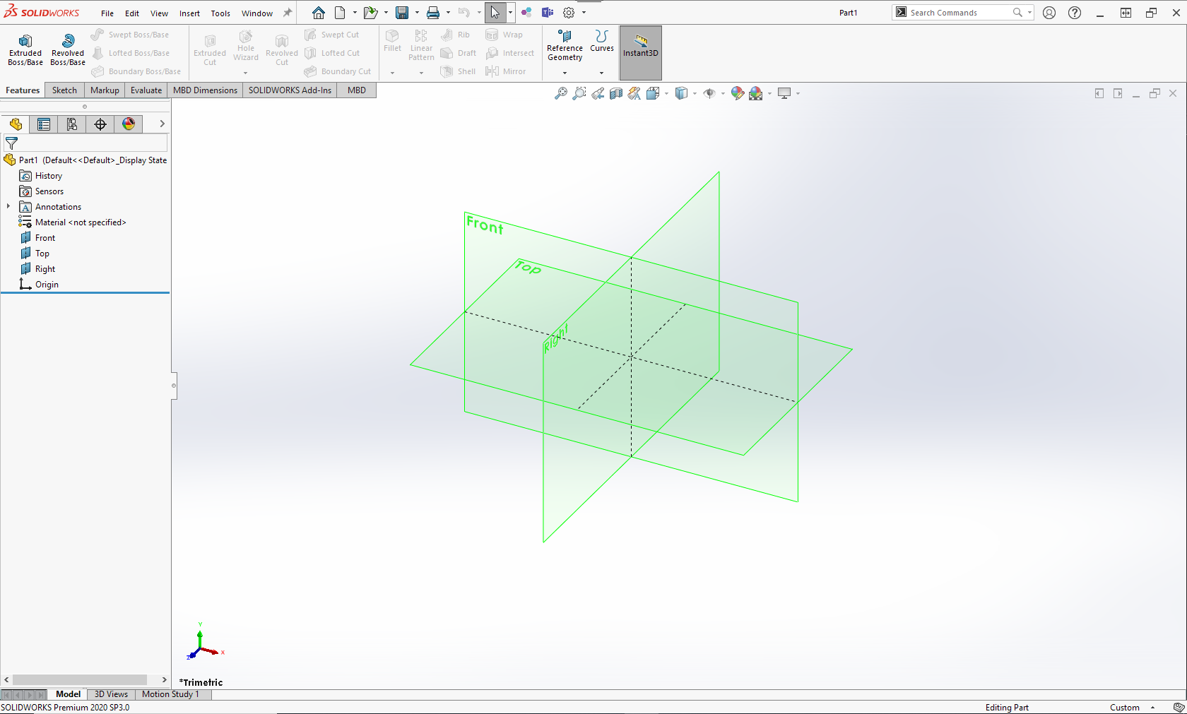
At this point, you should see an environment like the one shown below. You have now entered the SolidWorks workspace for a new part. The group of icons at the top of the screen is known as the ribbon. The list of icons at the left of the screen is known as the design tree. Depending on the version of SolidWorks you are using, there might not be the green planes shown in the workspace. That is not an issue. It is alright if there are no planes at this step.
2. Preparing a Sketching Plane
To start creating the sketch, click on the “Sketch” tab towards the upper left and then select the “Sketch” icon. A new message replaces the design tree, asking you to select a plane on which to create the sketch. At this step, planes should appear in the workspace. Click on any plane you desire and watch as the selected plane pans into view.
3. Creating a Sketch
As mentioned before, SolidWorks uses parametric modeling. This means that it assigns parameters to entities like lines and features of the sketch. As a result, it is necessary to assign the dimensions (measurements) while the sketch is being created using basic shapes.
For example, in the case of the bracket in this tutorial, it is easiest to start sketching the bottom of the bracket as a rectangle and assigning the appropriate dimensions to it.
In the “Sketch” tab of SolidWorks, select the rectangle icon. It defaults to a “Corner Rectangle.” You will notice a drop-down next to the rectangle icon with choices for different types of rectangle sketches. For the purposes of this tutorial, you will use “Corner Rectangle,” but any type of rectangle is fine.
Click the icon once, and then click anywhere in the workspace to start the rectangle sketch. Upon your first click in the workspace, the first corner of the rectangle is created and placed. Move your mouse cursor to a random location in the workspace and click a second time to denote the opposite corner. It doesn’t matter where you move your mouse cursor because the actual dimensions of the rectangle are specified in the next step. After the second click, the rectangle is created. Click the green checkmark in the design tree.
Note: There are several ways to move the workspace around when creating a 2D sketch in SolidWorks. For example, you can zoom in and out using the rotating wheel of your mouse. (You can also go to View > Modify > Zoom In/Out and use the cursor to zoom.) The placement of your mouse cursor will dictate where you zoom into and out of. Take time to get familiar with this. Furthermore, by holding “Ctrl” and pressing the mouse wheel at the same time, you can pan the workspace up, down, left, and right with your mouse. If you don’t have a mouse wheel, go to View > Modify > Pan, and use the pointer to pan view the workspace.
4. Adding Dimensions
The next step is adding dimensions, also known as “dimensioning.”
At the top of the screen in the ribbon, select “Smart Dimension.” Then click on one of the vertical lines of the rectangle and move your mouse. You will notice that a dimension is created and follows your mouse cursor. You can click again to place the dimension and edit the value of the dimension. Type in the value of the dimension and click “Enter” on your keyboard to set the dimension.
You have now dimensioned the height of the rectangle (0.75”). Repeat this process with one of the horizontal lines to dimension the width of the rectangle (1.75”).
Tip: SolidWorks understands units as well. You can type in the abbreviation “in,” and SolidWorks will understand that the value you are typing is in the units of inches. Just make sure that you’re consistent with your units across the part and that you select the correct units when you upload your file to our website for quoting.
5. Adding Lines to the Sketch
Now we’ll create another rectangle but this time using lines. Again, the philosophy here is to create lines or sketches first, and then add dimensions later. Therefore, you don’t have to be exact with the initial placement or lengths of the lines.
To create lines, click the “Line” icon directly above the “Corner Rectangle” icon. Next click on the top line of the rectangle to place the starting point of the line. Have this be more towards the left side of the rectangle. Move the mouse cursor up vertically and click again to set the ending point of the line. A yellow square with a vertical line will appear next to your cursor when your line is vertical. This helps you draw perfectly vertical lines. Depending on your version of SolidWorks, dotted guidelines may also appear. After the end point click, another line is automatically generated with its starting point being the ending point of the first line. Move the mouse cursor directly to the right and place the end point more towards the right side of the rectangle.
At this point, you will see a third line appear. Place the endpoint of the third line on the horizontal top line of the bottom rectangle. Make sure this third line is vertical like the first line. Click the “Esc” key on your keyboard to stop the auto-creation of more lines.
6. Trimming Entities
There are now two regions in this drawing: the tall top rectangle, and the wide bottom rectangle. To join these regions, it is necessary to get rid of the portion of the line separating them. Consider this portion of the line as an “Entity” that needs to be trimmed.
To do this, use the “Trim Entities” tool. This is used to “Trim” the portion of the line that is dividing the bottom of the sketch from the top of the sketch.
First, click the “Trim Entities” button in the ribbon. Click and hold on one side of the “Entity.” While holding the left mouse button, drag the cursor across the “Entity” and then release the left mouse button. This trims the “Entity” and combines the top region of the sketch with the bottom region of the sketch. Click the green checkmark in the design tree to finish this step.
7. Further Refining the Sketch
The next step in the sketching process is the refining of the geometry. Remember that the top of the bracket is rounded. A quick and effective way to do this is to create a circle whose perimeter is tangent to all three lines that were created in the previous step.
Notice the “Circle” icon directly to the right of the “Line” icon in the ribbon. Click the drop down and select “Perimeter Circle.” In the workspace, one by one, click the lines that were created in the previous step. This creates a circle tangent to all the selected lines. Use the “Trim Entities” tool again to get rid of the lines outside of the circle. Use it also to trim the bottom of the circle so that the sketch becomes one region again. Click the green checkmark in the design tree to finish this step.
8. Finishing Dimensions
Now that the rough outline of the sketch is created, it is time to add more dimensions. Instead of dimensioning lines, you will now add a dimension to specify the distance between two locations. This is helpful to add a total height to the sketch.
To do this, first click on “Smart Dimension.” Then, hover the mouse cursor over the very top of the circle. A small square should appear, representing the exact top of the sketch. Click there, and SolidWorks understands that as the first location of the dimension.
Next click on the horizontal line at the bottom of the drawing to denote the second location. Immediately a dimension is created to express the distance between the two locations. Move the cursor to position the dimension and click to set it. As before, type in the value of the total height of the drawing and press “Enter” on your keyboard.
Similarly, create a dimension that expresses the distance between the two tall vertical lines of the drawing. Press “Enter” after typing in the distance value. After pressing “Enter,” press “Esc” to exit the dimension tool.
9. Centering and Alignment
Finally, center the top portion of the drawing. An effective way of doing this is to make sure that the short horizontal lines on either side of the tall vertical lines are equal in length.
Select both horizontal lines at the same time. This can be done by clicking one line, and then clicking the other line while holding the “Ctrl” button on your keyboard. Notice new options that appear in the design tree. Select “Equal.” This forces the selected lines to have equal lengths, thus, making sure the sketch is centered. Click the green checkmark in the design tree to finish this step.
You have finished creating a fully-dimensioned 2D sketch in SolidWorks, accurately parameterizing the outline of the bracket!
Now That You’re a Sketching Expert…
Try to apply the fundamentals from this sketching tutorial to your own designs. Or, continue on to the second part of this beginner’s guide to finish the bracket design and learn how to turn this 2D sketch in SolidWorks into a 3D part.
Regardless of how many years someone has used CAD, they never stop being a student. Learning and practicing CAD is a lifelong endeavor so keep designing and exploring, and keep sending us those designs to make into a reality!
Custom CNC, laser, and waterjet cutting are only the beginning. Other services offered by SendCutSend include countersinking, hardware insertion, tapping, bending, and finishing. Visit the following link to learn of the different materials that are offered:
You can also get quick and instant pricing by taking advantage of the parts builder, SendCutSend design services, or custom quotes for projects with unique needs or requirements.
FAQs Around SolidWorks Sketching
How to change scale in a SolidWorks drawing
To scale a sketch in SolidWorks, you can use the “Scale Entities” feature when inside “Edit Sketch” mode. Or, you can navigate to Tools > Sketch Tools > Scale.
It will give you the option to select a scale factor, as well as a base point to serve as a reference point around which the sketch will scale.
How to link drawings to parts in SolidWorks
The “extrude” feature found in SolidWorks and many CAD programs allows a drawing to be converted to a 3D representation. Any changes to the original drawing are linked to the resulting 3D part.
To learn how to convert a 2D sketch into a 3D part, reference the following article:
How to export 2D drawings
To learn how to export drawings to DXF in SolidWorks, visit the following article:
