
In this tutorial we’re going to show you how to unite and exclude objects in Inkscape for laser-cutting.
Making sure your objects are combined correctly is important for laser cutting. The laser will read any path in the file, whether it’s stray or disconnected from the rest of the object, and attempt to laser cut the path, ruining your product in the process. Don’t worry though. These things are super easy to clean up if you follow our tutorial.
Let’s look under the hood
Tidying up your objects for the purpose of laser cutting is best shown by example. Pretend you’re me and you want your logo cut out on a nice little stand. You’d start with something like this:

Looks pretty good, right? Well, before we get ahead of ourselves, let’s view our design in “outline display mode.” I suggest doing this numerous times as you’re designing and getting your file ready for laser cutting.
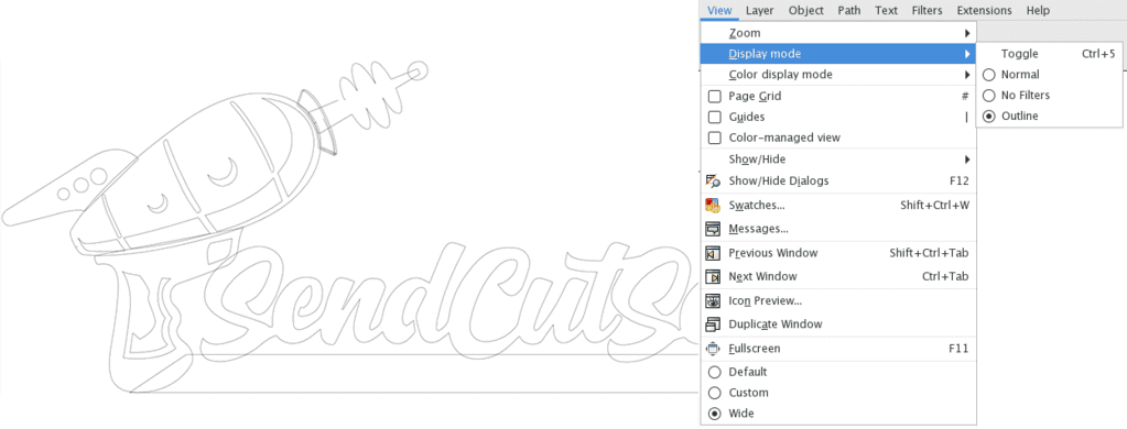
Here’s where it gets messy. See all those overlapping lines? The laser will attempt to cut all of them even though they’re overlapping and it’s not possible. I have multiple objects all piled on top of one another, and I see a couple of stray points, an open contour, and a line that isn’t connected. I’ll need to fix those issues before I send this file to the laser.
Fixing open contours
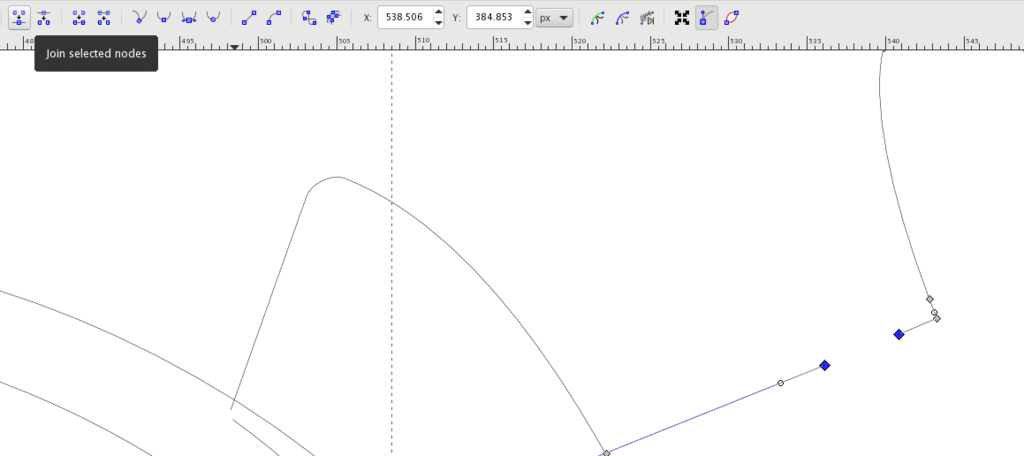
Before I combine my shapes, I need to fix that open contour, or broken path. Using the “edit path by nodes” tool (F2), I will select the two nodes that I want to join. In the top toolbar, I’ll click the “join selected nodes” button.
Merging shapes
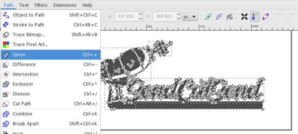
Now that I have a continuous path I can merge my shapes. Using the “edit path by nodes” tool (F2) again, I’ll select all the shapes. In the Path menu, I’ll select Union. This will merge all my shapes into one. You can double-check that your objects have merged correctly by viewing the file in “outline display mode” again. The lines should no longer be overlapping and the object will be laser cut cleanly without any unwanted cuts.
Dividing/excluding shapes
The example above was pretty simple because I had already made use of the “exclude” tool. Now is a good time to talk about using this. The “division” and “exclude” tools let you reverse one shape out of another while making it all one object. For this example we’ll just look at the laser gun in our design.
To start, I basically have one gray shape that has white shapes layered on top. The white shapes are what I want to have cut out of the material by the laser-cutter. Now if I select all and apply black, it becomes obvious that there aren’t actually cut lines for the holes in the part. It’s just layered shapes. I need to cut the white shapes out of the laser gun in Inkscape so when the part is sent to the laser, the correct paths are recognized for cutting.
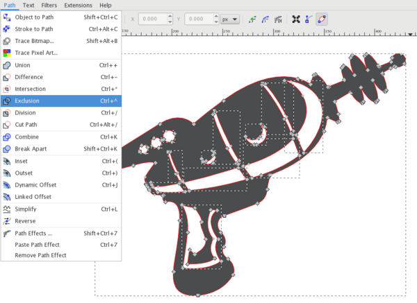
We’re going to start by using the “edit path by nodes tool” (F2) to select all the shapes. Then under the “path” menu, I’m selecting “exclusion.” The exclusion tool will cut the white shapes out of the gray, creating one cohesive shape that I can send to the laser.
I’m going to view the file in “outline display” mode one last time and move the object around. This is just to make sure the exclusion tool didn’t leave anything behind or create any empty objects.
If you have questions about merging and welding shapes with other softwares, we are continually updating our blog with resources to help you get the most out of your SendCutSend experience.
