The best way to create a successful design for laser cutting is to use one of SendCutSend’s Recommended Software. We’ve put together our list based on ease of use, quality of the export, and accessibility. You’ll notice that Rhino3D is not on our preferred software list. This is because when compared to other CAD and 2D design software, Rhino3D produces unreliable exports and inconsistent final files. We understand that it’s not always possible to work with unfamiliar software, so if you need to use Rhino3D for your design process, the following guide will walk you through creating a successful Rhino3D export for manufacturing at SendCutSend.
Step by Step Guide To a Rhino3D DXF Export
Step 1: View design top-down
Getting a great DXF export from Rhino3D starts with having your design in the “Top” viewport. If the top viewport doesn’t show your part from a top-down view, use the rotate command from the other viewports and lay the design down flat.
Step 2: Isolate geometry
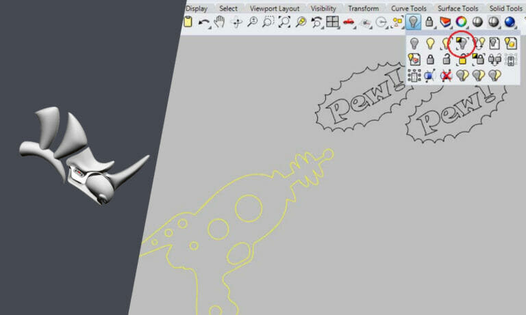
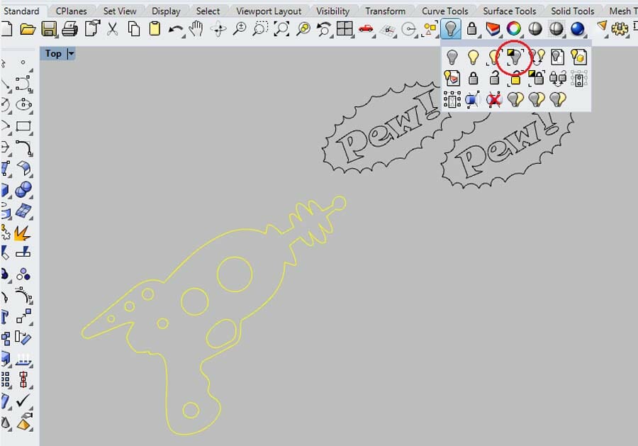
You’ll need to isolate the geometry that you want to export. This is accomplished by selecting that geometry and using the “Isolate” tool, shown in the image below.
Step 3: Close all contours
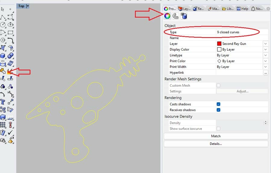
While SendCutSend doesn’t require that you join your geometry, it does require that the geometry be closed contours. If you “select all” (Ctrl + A), followed by the “Join” command, you’ll be able to see if your curves are closed by looking at the “Object” portion of the “Properties” tab. This is a great way to identify hard-to-see issues with geometry before uploading it.
Step 4: Export DXF
With all of the geometry selected, go to “File>Export Selected.” This will allow you to name the file and, most importantly, select “Save as Type.” Note that SendCutSend requires that files exported from Rhino3D are AutoCAD Drawing Exchange (*.dxf) file types.
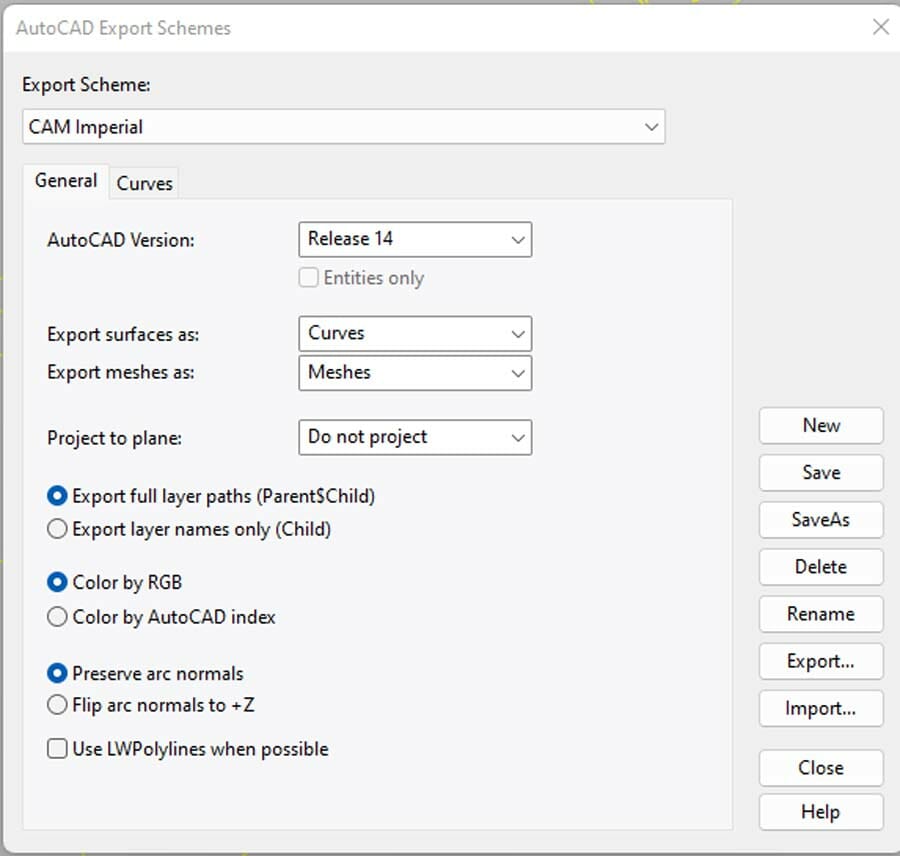
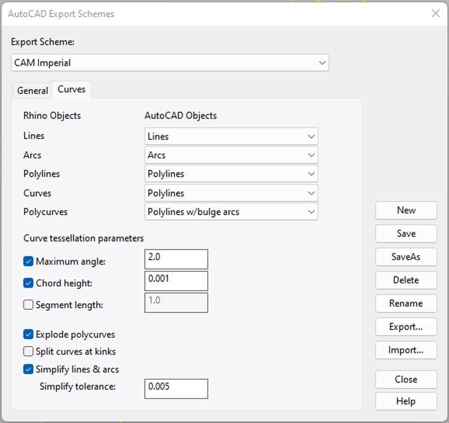
Selecting “Save as Type” will bring up the export options window. If your file was created in millimeters, select “CAM Metric” from the drop-down menu. If your design was created in inches, select “CAM Imperial” from the drop-down. With the scheme selected, click the “Edit Schemes …” button.
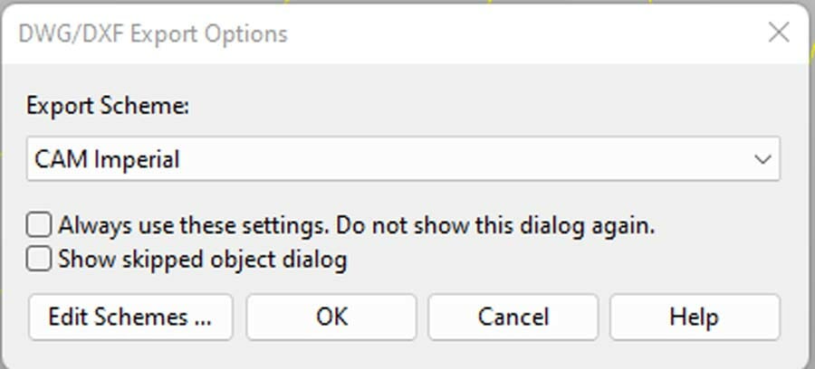
The opened tabs should look like the images below. If needed, make any changes and then click “Save,” followed by “Close.”
Step 5: Confirm file is correct
Click “OK” and your design will save as a DXF. It’s always a good idea to reopen the file in a new Rhino3D window to make sure it looks the way you intended. While you’re checking the design, make sure it fits all our guidelines for the material type and machining process. You can use our Pre-Flight Checklist to make sure the file fits our general requirements:
- File is a two-dimensional vector format file
- All holes and cutouts are at least 50% material thickness (no less than .063″ for waterjet cut parts)
- File is built at a 1:1 scale, preferably in inch-units
- All objects are on the same layer
- All stray points, duplicate lines, empty objects and text areas have been removed
- No shapes have open contours
- All shapes have been united, combined or merged
- All text has been converted to outlines or paths
- Cut-out text (reversed text) has bridges or has been stencilized
- “Create PDF compatible file” needs to be checked when saving as an .ai
Upload Your Rhino3D DXF for Instant Quoting
Once you have completed your design and checked the file against our guidelines, upload the DXF to our instant pricing tool. We ship most standard orders in 2-4 business days, but be sure to check how additional processes can add to the production time.
If you’re interested in utilizing one of SendCutSend’s recommended software and don’t know how to get started, check out our blog with resources on designing and exporting in all our recommended CAD and illustration software.
