Reading an engineering drawing is crucial to be able to properly convey the design intent of a sheet metal part. Without this ability, designers and (most) fabricators won’t be able to work together to produce acceptable parts, and you could wind up with a pile of useless laser cut parts that don’t work.
Fortunately, SendCutSend doesn’t require drawings, and can fabricate parts directly from CAD (computer aided design) models. However, many fabricators still require them, especially for complicated or precise tolerance parts. This article will expand on the anatomy of an engineering drawing, and how to properly read an engineering drawing. With this understanding, designers can take the first steps towards generating these detailed and vital documents for their own parts or new fabricators can learn how to make parts from them.

Engineering Part Drawing vs Engineering Assembly Drawing
There are several types of engineering drawings such as weldment, electrical, hydraulic routing, etc. The two most common, and the two addressed in this article are: part drawings and assembly drawings. These are used for fabrication of parts and assemblies. The main difference is in the scope contained in the drawing.
An engineering assembly drawing includes top level details required to assemble a series of parts together correctly. This will usually include overall dimensions of the finished assembly, views of a completed assembly, a labeled (aka ballooned) view detailing each part in the assembly, and a bill of materials.


Above an assembly drawing is shown next to an example assembly. Note the lack of detailed dimensions for the parts since an assembly drawing is for putting parts together, not creating them.
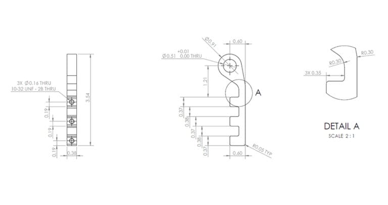
A engineering part drawing on the other hand is limited in scope to a single inseparable part, usually made from a single piece of material. The part drawing will have all the details required to fabricate or modify a part as needed for the intended design. These details include the materials, material finish (such as powder coating, anodizing, metal plating, etc.), detailed dimensions, tolerances, etc.
Above is an example of a part drawing. All of the details required to fabricate this part are included in the drawing. Each of the major components discussed in detail below is highlighted.
Anatomy of an Engineering Drawing
Title Block
The title block is in the lower right corner of an Engineering drawing, and contains a ton of important information. Some of the important information in every title block is the part name, scale of the drawing, and number of pages in the drawing. While not always included, it is best practice to also include the default tolerances, as well as the names or initials of the designer, drafter or who generated the drawing, and drawing approver.

The enlarged title block shows all the details contained in it. Many of the details in the title block are critical for traceability of approvals, as well as giving an overview of the part details.
Revision Block/Table
A revision table is found in the upper right corner of some drawings. It keeps track of any revisions made to a drawing either by a designer, or as part of a process to revise the drawing to “as-built”, see below for a description of this modification process. The revision block will list the revision name, a brief text description of the modification(s) made, and usually a location or zone where the change is located.
“As-built” is exactly what it sounds like, sometimes minor modifications have to be made to parts or systems to conform to field conditions or part interferences not accounted for in the design. Typically these modifications will need to be reviewed and approved by the designer or engineer, before being implemented into a revised drawing.

The revision block is shown bordered in green, and details changes made after a drawing is formally released.
Bill of Materials (aka BOM)
A bill of materials describes all the parts needed in an assembly. Typically it will include: item number in drawing, part number, manufacturer, description, quantity in the assembly. Depending on the size of an assembly, the bill of materials can actually take up multiple pages by itself. Think of the BOM as a checklist or shopping list to be able to make the assembly.

The bill of materials shown above outlines all the parts used in an assembly.
Notes
The notes section is in the upper left corner of the first page of a drawing. It can contain any number of useful pieces of information such as required engravings/markings, surface finish (if not defined elsewhere), storage requirements, handling requirements, cleanliness requirements, etc. Basically anything that isn’t common to most any part, or might be unique would be listed in the notes section.

Above the notes are highlighted, anything not conveyed in the standardized drawing template can be detailed here.
Grid Reference Border
The outer perimeter of the drawing contains a grid reference for identifying different areas of the drawing. The vertical sections of the drawing are divided into lettered segments, while the horizontal sections are divided into numerical segments.

In the image above, the revision block calls out a change to the holes in the part, the zone indicates where on the drawing it is located. The change occurred to the hole callout located at B4.
Engineering drawings are a very important way to convey technical information between designers and fabricators. These documents outline all the information needed to fabricate and/or assemble parts. A well thought out drawing eliminates ambiguity, and clearly details what is necessary to pass quality inspections, and have a fully functioning part. While SendCutSend doesn’t require drawings for our manufacturing processes, they are still a useful tool in any designer’s belt to be able to effectively communicate. As can be seen above, there is a bit more to engineering drawings than slapping some dimensions onto paper, and they should be approached with a deliberate attention to detail regardless of if they are being drawn or read.
If you have any questions, feel free to reach out to us at support@sendcutsend.com. If you’re curious how else we can help, check out this brief article: What SCS can do for you. When you’re ready, upload your design and get an instant quote today!
FAQs on Engineering Drawings
- What is a bill of materials/What is a BOM?
- A bill of materials (also known as a BOM) is a list of parts and/or subassemblies that are combined into an assembly. For each part in the BOM it includes: part number, manufacturer, description, and quantity.
- What is drafting?
- Drafting is the act of creating engineering drawings. It conveys the technical intent of the design to the fabricator.
- What is a T-square?
- A t-square is a “T” shaped tool used by manual drafters to draw straight lines on a drafting table. Think of it as a long straight edge that hooks over the edge of a table to allow quick and easy vertical or horizontal lines.
- Why do we still create engineering drawings?
- While SendCutSend’s services don’t require engineering drawings, more complex services such as machining or welding often still do. Often just the 3D CAD model isn’t enough to convey the full intent of the design to a fabricator, especially if post processing options such as cleanliness standards or part marking are required.


