Everyone has had that one last fastener on a part that is impossible to get in place, or a fastener that is just so tiny it’s difficult to even hold, let alone work with. More often than not, these painful experiences can be avoided with a bit of extra effort by the designer.
This article will be outlining some common areas and gotchas to watch for to make sure fasteners are accessible and easy to work with.
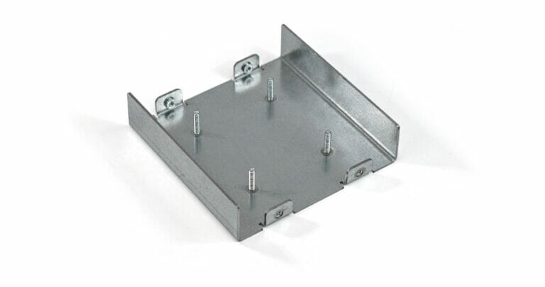
If you missed it, SendCutSend now offers hardware installation using PEM fasteners.
While there is no substitute for experience in spotting these problem areas, a fast way to get better at designing is by building! The hands-on experience of assembling and/or fabricating designs is the best teacher.
Fastener Placement
Fasteners are time consuming for most designers. There are many things that have to be considered: are they strong enough, is there enough material around them to support the forces they will be resisting, corrosion, cost, etc. With all these things in mind, the most important consideration should be: can the fastener be installed?
A fastener isn’t useful if it is physically impossible to put it where it is intended to go. CAD models are a great start towards visualizing where a fastener can be placed, but they don’t tell the whole story. Even if an exact model of the correct fastener stackup is used, which is a great idea when time permits*, it is vital to keep in mind the tool clearance needed to install those fasteners.
The type of fastener will drive which tool will be used. A hex head bolt will require a different tool from a socket head cap screw.
As an example, the hex head bolt will use either a wrench or a socket to install it. The space requirements to effectively use each of these is quite different. For instance, a socket can be used inside a properly sized counterbored hole, while a wrench cannot. On the other hand, if there is minimal clearance along the axial direction of the bolt, a wrench might be the preferred approach.
Keep these things in mind as fasteners are located within the part. Visualizing the installation process, or even making a quick mockup can save a lot of effort and frustration later on in the assembly process.
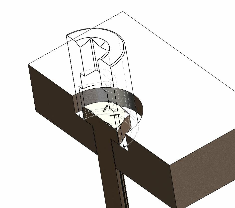
Note in the above example that a socket has plenty of clearance in the counterbored hole, but the recessed bolt would be inaccessible to a wrench.
Another consideration should be how valuable is the time required for assembly. If the design is a prototype, or being assembled for a personal project, it’s likely that taking 10 minutes to install a single fastener isn’t a large concern. However, if the product is assembled in large quantities on an assembly line, even a single difficult fastener will rapidly increase the per part cost and the likelihood of both errors and damaged parts. Here, the consideration of possible vs practical has to be taken into account. Just because a fastener is possible to install, doesn’t mean it is a practical choice.
One final consideration with respect to fastener placement, is looking beyond the fastener, to the other components of the fastener stackup. If using a tapped hole, then a washer is not utilized on the side of the joint opposite the fastener head, thus backside clearance to accommodate one isn’t required.
However, if a nut and washer are used, then the size and diameter tolerance of those must be taken into account. Washers should lay flat against the mating surfaces in order to work properly. For especially tight spots, a clipped washer can be used. Clipped washers are flat on one side to fit into tight spaces.
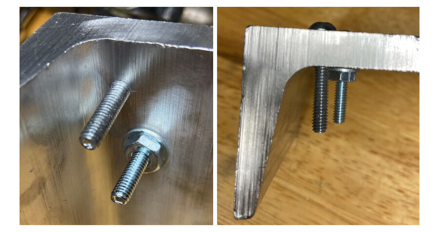
In the above example, a tapped fastener is able to get much closer to the interior filet of the C-channel because spacing for a washer isn’t required.
*Bonus tip: Many new designers preserve explicitly modeled threads within CAD models. While threads are cosmetically pleasing, they don’t offer much value, and cost quite a bit in both model size and how much computing power it takes to manipulate a model. Consider removing cosmetic threads from CAD models to take advantage of the performance boost!
Fastener Size
How small is too small? This varies by person, primarily with hand size and dexterity, but also varies with the tools available for the task. About size #6 or larger (M4 for metric) is a comfortable option for most.
The opposite extreme of the spectrum can cause its own set of problems. If a fastener is overly large, it makes both the fastener and the tools harder to handle. When a wrench weighs 10+ lbs, it is much harder to handle, especially for prolonged periods or while in awkward positions. It is a very easy mistake to lose track of the scale when working within CAD, as the parts can be zoomed in or out to a point they are comfortable to look at. Unfortunately, the real fasteners can’t be scaled up or down to make them easier to work with.
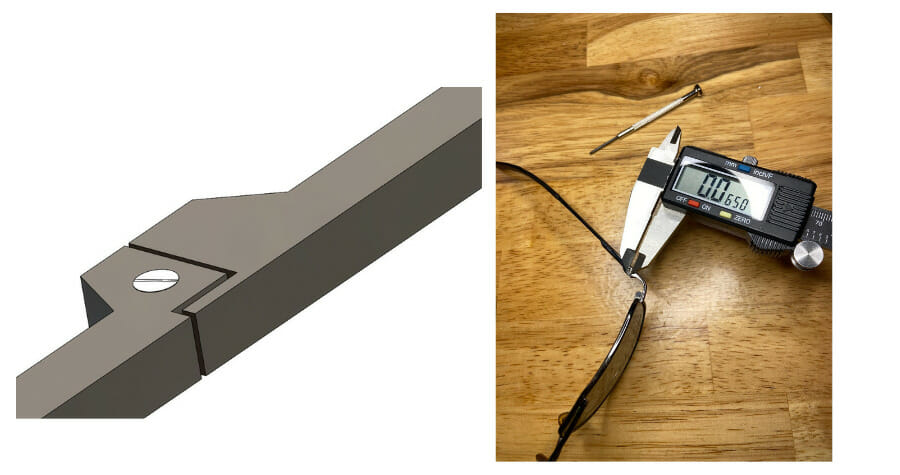
The CAD on the left is zoomed in very close to the glasses, and the scale of the fastener is lost without a reference. Keep this in mind when working with CAD to maintain comfortable sized fasteners when feasible.
Interfering Parts
When deciding on proper fastener placement, it is also important to keep in mind the environment the design will be installed in, or if there are other parts that might get in the way of proper tool access.
For example, will the design bolt to the floor in the corner of a room? If so, make sure enough space is left between the design and the adjacent walls. For more complicated designs, there could also be conflict in order of assembly. While this is an additional consideration, it can also be a benefit. Order of assembly can sometimes allow an otherwise inaccessible fastener to be installed if the conflicting parts are installed later in the process, after that access is no longer required.
To help with visualization, think through the assembly process taking notes on proper order of assembly. A helpful technique is to hide all parts in a CAD assembly, and show them one at a time in the order of assembly. Look at each fastener location individually with only the previously installed parts shown, keeping in mind all the previously discussed considerations as each fastener location is scrutinized for conflicts.
If it seems like a particular design has no alternatives, consider involving a coworker or friend. Often a fresh perspective will introduce new design ideas and alternatives that being too close to the project will prevent the designer from seeing. Another option is to consider another joint technique. Perhaps a weld, solder, or adhesive joint might work in place of a bolted joint. Though each of these techniques also has the potential for tool clearance considerations like fasteners do.
As an example, welding has to have enough access to the joint in both clearance and angle of the weld tool for a proper weld. Visualization, mockups, and subsystem prototypes are all very beneficial tools in a designer’s toolbelt.
Using Fasteners In Your Design Without Frustration
Fasteners are a critical part to any design, quite literally they hold the whole thing together! While it is tempting to simply throw them into a design wherever is easiest, what is easiest for the designer is often not what is easiest for the fabricator or best for the design. Always remember to keep these things in mind:
- What tool will be used to install a fastener, as well as the total fastener stackup
- Make sure enough space is available to easily install each fastener
- Try to avoid fasteners that are either extremely small or overly large
- Keep both installation location and order of assembly in mind to make sure enough space is available for each fastener location.
Try these techniques out on your next project so you never have to deal with frustrating fasteners again.
If you have any questions, feel free to reach out to our support team. When you’re ready, upload your design and get instant pricing today!
If you are new to SendCutSend, here’s a handy step-by-step guide on how to order parts from us: How to Order Parts from SendCutSend (spoiler alert: it’s super simple and intuitive to order from us)


