Somebody has handed you a broken part, a known working part, or even no part and you must come up with the blueprint to make another. Reverse engineering existing parts is no small task, but can be done successfully if you follow a few simple tips. The following article will show you how to reverse engineer existing parts in as few iterations as possible.
Was the Part Made With Imperial or Metric Units?
A good set of inch/metric calipers are essential to reverse engineering. Before you begin the engineering process, you will need to know if the part was made originally using imperial or metric units. If you’re working with a large part, a dual scale ruler or tape measure can help.
Figuring out the metric origin of the product can give you a head start on the reverse engineering process.. Keep in mind that there is often a blending of units. Parts might have their fasteners in one unit, but the rest could be in a different unit.

This is a popular design strategy for products that may be entering or exiting the US:
- An entire part may be designed in metric but produced with inch-standard pipe, square tubing, sheet, or bar stock.
- Designs often use off-the-shelf parts that may be in another unit, as they can be more readily available and more cost-effective.
Was the part over-engineered or under-engineered?
Another important aspect of reverse engineering is determining and dealing with whether the original part was over or under-engineered.
If you are reverse engineering a part that has broken, sometimes it’s clear why it has broken so you may be tempted to improve on the design. Before you do so, consider why the part was made the way it was and the benefits there may have been at the time.
For example, know what to look for if a part was mechanically punched out.
- Thicker metals are more costly to punch out.
- Companies skimp on metal thickness, so a thicker replacement part can be more viable.
In this case, you could go ahead and make it thicker.
If possible, consider summing two parts into one, or one part into separate parts because an easier to manufacture solution may be possible.
What Was the Origin of the Part?
Next, you can think about how you would begin designing the part if you were the original designer. Many parts have an origin, which might be the key feature. This could be a bearing, a mounting hole, a bend, or a critical mating edge. Designing the part out from that point can make other measurements fall in line because reference dimensions are often taken from the key feature.
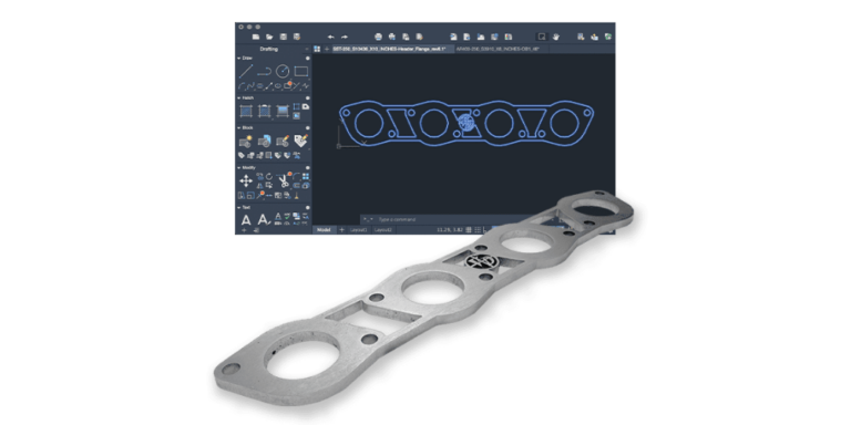
Utilize CAD Software and Scanners
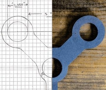
CAD is a great tool for reverse engineering and going between a design and the real world. Many businesses and homes already have the tools to go from a computer design to a real part and back again. A printer and a scanner are hidden weapons in design. (Just make sure you have your scaling set properly!)
Most CAD programs have the feature to import a reference image. Using a scanner to import images is more accurate than a digital camera as they transfer shapes on a plan. Using images from a digital camera can distort the images. When you use a scanner, you can design the part directly over the scanned image.
When using a scanner, some brackets may have complex shapes that can be a bit finicky to get right. No matter how many different ways you measure the distance between a feature and some suspected reference dimension, it might just be arbitrary. Curved geometries benefit greatly from this trick.
Larger parts can be scanned in sections and “stitched” together in an image editing software. Simple permanent marker lines or markings can make great indexing points on the tangible part as you digitize it.
Once you have designed your part, a simple printer can be used to test fit any designed parts. If a more useful test part is needed, the design can be transferred onto cardstock or cardboard. This way pivot points and clearances can be tested, and larger designs can be printed with indexing marks as well. We would recommend a simple hobby knife and painter’s tape to cut out the parts and to stitch sections together or to transfer the template.
Final Tips for Reverse Engineering
- After all the flange dimensions and photos are taken, consider flattening a sheet metal part and checking its dimensions against your generated sheet metal flat pattern.
- Model the features you are trying to fit the part around.
- Cardboard can be a good substitute for ⅛” sheet metal.
- Consider scaling down and printing out bent sheet metal parts and try to bend them. Clearance issues and bolt holes can be tested.
Our laser cutting, CNC bending, and other manufacturing services here at SendCutSend are ideal for prototyping and recreating reverse engineered parts.
Be sure to read our other tutorials for utilizing these services and check your parts fit against our guidelines before placing your order!


