Sheet metal bending is the process of using a CNC or manual brake to bend or form sheet metal into 3-dimensional shapes. What sounds like a relatively simple process actually involves a significant amount of complicated math, preparation, and terminology. We’ve covered a lot of information on designing for sheet metal bending and arranging geometry around bend lines, but understanding the terminology surrounding sheet metal bending will allow you to understand exactly what’s happening to your part during bending and why our guidelines are set up the way they are.
One of the more difficult concepts to grasp in sheet metal bending is the k-factor. This article and the accompanying video will explain everything you need to know about the k-factor and how it’s calculated.
What is K-Factor in Sheet Metal Bending?
The k-factor is the ratio between the thickness of the metal being bent and something called the “neutral axis/line.” The neutral axis is an invisible line that splits the thickness of the metal in half and runs all the way through the part. The neutral line represents the material that doesn’t actually change or compress during the bending process, but just moves in the direction of the bend. The k-factor uses this relationship between the neutral axis and the thickness to determine how much the metal on the inside of the bend will compress and how much the metal on the outside of the bend will expand, changing the length of the overall part.
Knowing the k-factor of a part prior to forming is crucial to the bending process because it determines the tooling and angle in the brake. But beyond that, it’s important for you to know the k-factor of your part before you even finalize the design. Because the bending of a part changes its length, you will need to compensate for that expansion and compression in the design stage of your part.
4 Terms to Better Understand the K-Factor in Bending
K-factor as a whole is a difficult concept to wrap your head around without understanding all its unique factors. There are four key terms involved in understanding the k-factor and how it’s calculated: apex, setback point, neutral line/axis, and the bend radius. Later on, we will be showing the formulas necessary to calculate k-factor and bend allowance, which include all of these terms expressed as values. Although you definitely don’t need to have these formulas or these values memorized in order to successfully design a bent sheet metal part, having the information in your back pocket can help you better understand how sheet metal behaves in the brake and how to adjust your design to compensate for its movement.
Let’s break down each of these four concepts so you can see how they affect the k-factor and the end result for your bent sheet metal part.
Apex
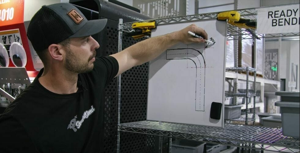
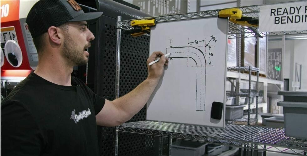
Let’s start with talking about the basic terminology of bending and flanges. In this example, we have a single bend that’s 90 degrees with two flanges: a flange on the top, a flange on the bottom, and a bend in the middle.
The first part of sheet metal bending terminology that we want to talk about is often called the apex or the mold point, and that’s going to be the very center of the bend. We’ll write apex here to indicate that. The apex is the theoretical point that’s off the tangents of the bend. So if we were to have a perfect corner without a radius, the point where the corners meet is where the apex or the mold point would be.
Setback Point
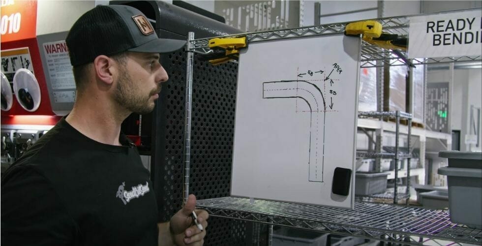
The next term that we want to talk about is the setback point (labeled “SB” in the below example). The setback point is the distance from the apex back to where the bend line is going to be, where the end of our bend goes into the flange. The bend in our example has two setback points: we have one on each side of the bend that are the same exact distance. There are two things that really affect the setback: the angle to which you’re bending the material and the radius in which you’re bending it. If we change the radius, we move the bend line down, and if we change the angle, we move our apex.
Neutral Line
The next piece of sheet metal bending terminology we’re going to talk about is our neutral line (indicated by the dotted line in this example). Our neutral line is the line that runs through the whole center of the part, so it’s half of the thickness of the part. It’s referred to as the “neutral” line because during bending, the material on the neutral line doesn’t get compressed or expanded. The neutral line itself just moves up toward the inside of the bend as the part is being formed.
Bend Radius
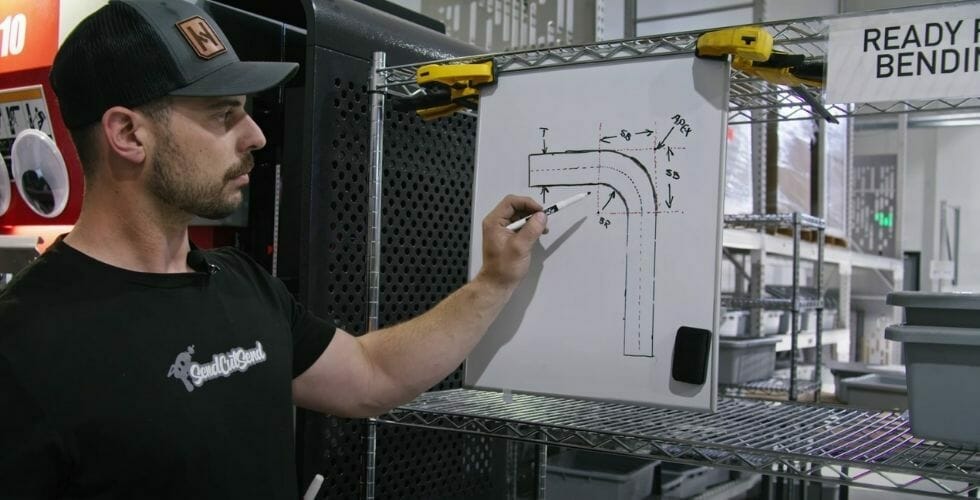
We have one other term to discuss before talking about the k-factor, which is our bend radius. The bend radius is measured on the inside of the part, not on the outside of the part. The bend radius is measured on the inside of the part because the part goes under compression and tension. The inside of this part is in compression. This area is actually compressed and formed to create the inside of the bend. And then the outside of the bend is in tension. So when we bend, we actually end up deforming the area with the bend, and the area under tension ends up moving inward towards the neutral line.
To exaggerate this, stretching the outside area that’s under tension, we end up thinning it, which causes our neutral line also to shift inwards. This shift inwards and the thinning is where we get the term “k-factor” from. The k-factor is equal to that new reduced thickness over the overall original thickness.
Understanding How K Factor Works for Sheet Metal Bending
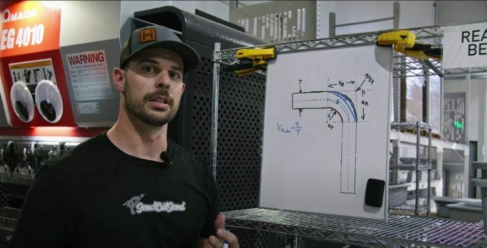
These concepts can be difficult to grasp just by reading about them or looking at pictures. Especially with a complicated subject like sheet metal bending, it’s often easier to understand by watching it happen in real-time. In the following video, Jake walks you through every single term and concept we’ve mentioned here, using a simple bent part as an example.
K-factor isn’t the only sheet metal bending concept that can be tricky to understand. Everything about forming and bending feels a bit like a mystic art. But we want to make sure that you know exactly what’s happening to your part during every step of the fabrication process, including bending and forming. Luckily, we’ve created a whole series of videos demystifying sheet metal bending with real application examples and simple explanations. The above k-factor video is part of this series. Covering everything from calculating bend deduction to configuring bends in our app, the nine video series will show you everything you need to know to design your first bent sheet metal part.
How to Calculate K-factor: Steps and Formula
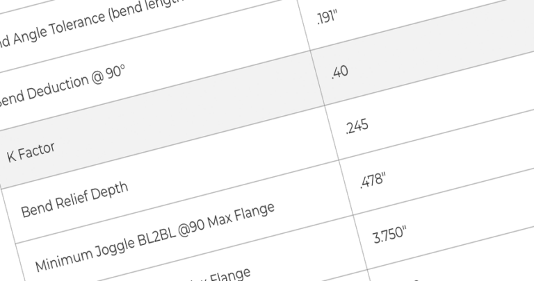
The K Factor is a critical ratio used in calculating the Bend Allowance (amount of stretch). The formula below shows this relationship between the centerline thickness (t) in the middle of the bend and starting material thickness (MT).
K=(t/MT)
T = Centerline thickness in bend
MT = Material Thickness

Here’s the only problem with all of this: it’s a lot of math. We don’t think you should feel like you’re solving rocket science problems when you’re just trying to make cool stuff, so we have eliminated the need for you to do all this math yourself. We have a super simple bending calculator which allows you to just put in your part information and it’ll spit out all the important values you need to know for adjusting your design. You can even verify that the design looks correct using the built in 3D model viewer.
K-factor vs. Y-Factor
The biggest difference between the k-factor and the y-factor in sheet metal bending is that the y-factor takes the internal stresses of the material into account more so than the k-factor does. This means that calculations involving the y-factor are slightly more accurate than those involving k-factor, but also quite a bit more complicated and uses different calculations for other values in bending, such as bend allowance.
Calculating the y-factor for a bent sheet metal part is really only necessary for highly complicated bends in unique materials, and most shops and machinists prefer to use k-factor as the industry standard.
Utilizing the Bending Calculator
We want to stress again the importance of using our sheet metal bending calculator. Without using this tool, you may not be able to compensate for the compression and expansion of the metal in your part accurately enough. You could end up with flanges that are too long and out of tolerance with your project. By using the bending calculator, you can save yourself days of headache and redesigns with just a few seconds of preparation. Simply input your material, chosen thickness, and flange and base length, and the calculator will do all of the work for you. Again, make sure to utilize this tool before uploading your final design for machining.
If you have any other questions about sheet metal bending terminology or SendCutSend’s online CNC bending service, check out our bending guidelines.


