Reference the chart below to learn more about our Cold Rolled and HRP&O offerings. For further information about each steel, reference the individual material pages linked in the table.
We guarantee awesome quality parts. If you’re not 100% happy, we’ll give you a refund or remake on the spot – no questions, no hassle.
We take pride in our customer service, quality, and continual innovation with new products and services. You’re in good hands with SendCutSend.
We accept .ai, .dxf, .dwg, .eps, .stp, and .step
Customize one of our simple parts templates

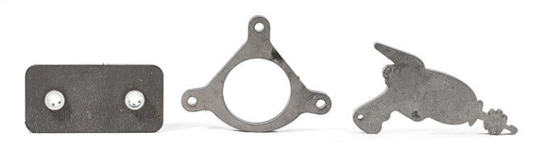
Mild steel is the workhorse of sheet metal fabrication — strong, weldable, affordable, and incredibly versatile. At SendCutSend, we offer several common mild steel grades including 1008, A36, and A36/A1018, all laser cut with ±.005″ precision and available with a range of secondary services. Below, we break down the essentials of mild steel, how its grades compare, and how to design your parts for reliable performance and clean fabrication.
Mild steel is a low-carbon steel containing roughly 0.05–0.25% carbon, offering a balance of strength, ductility, and weldability. It’s the backbone of the metal fabrication world, used in everything from automotive brackets and fixtures to furniture and machinery. Because of its low carbon content, mild steel is easy to shape, cut, and weld — making it ideal for both prototyping and production parts.
Mild steel combines strength, formability, and cost-effectiveness. Typical properties (vary by grade):
It’s strong enough for structural use yet soft enough to bend or tap easily.
Each grade of mild steel serves a slightly different purpose:
All three are laser cut with the same ±.005″ precision and support SendCutSend’s bending, tapping, and coating services. If you’re not sure which is right for your design, explore each material’s dedicated page in our Material Catalog.
Mild steel offers higher strength than aluminum and better formability than stainless, but requires protective coatings for corrosion resistance.
For more comparisons, see our Metal Comparison Guides.
Mild steel laser cuts exceptionally well, producing clean edges and tight tolerances.
Proper design for kerf and feature size ensures a perfect fit during assembly — see our Design Guidelines for details.
Yes, mild steel bends cleanly and consistently, especially in thinner gauges.
Check our Bending Guidelines for recommended radii and clearances by thickness.
Mild steel is one of the easiest metals to weld.
Because it welds so predictably, it’s a go-to material for custom brackets, roll cages, and structural assemblies.
Since mild steel is prone to oxidation, protective coatings are highly recommended. At SendCutSend, you can choose from several finishing services:
Review SendCutSend’s services guidelines before adding additional services to your laser cut mild steel parts.
Mild steel is strong and resilient, but it will oxidize (rust) if left unprotected.
Protective finishes make mild steel a long-term performer for both indoor and outdoor parts.
Keep strength, bendability, and coating needs in mind during design.
For more fabrication-specific details, review our Design Guidelines.
Mild steel is the all-purpose backbone of fabrication — affordable, predictable, and easy to work with. Whether you need strength (A36), formability (1008), or precision (A36/A1018), SendCutSend laser cuts your parts with ±.005″ accuracy and offers bending, coating, and hardware services to deliver a ready-to-assemble product. Explore all three mild steel grades in our Material Catalog to find the right fit for your project.