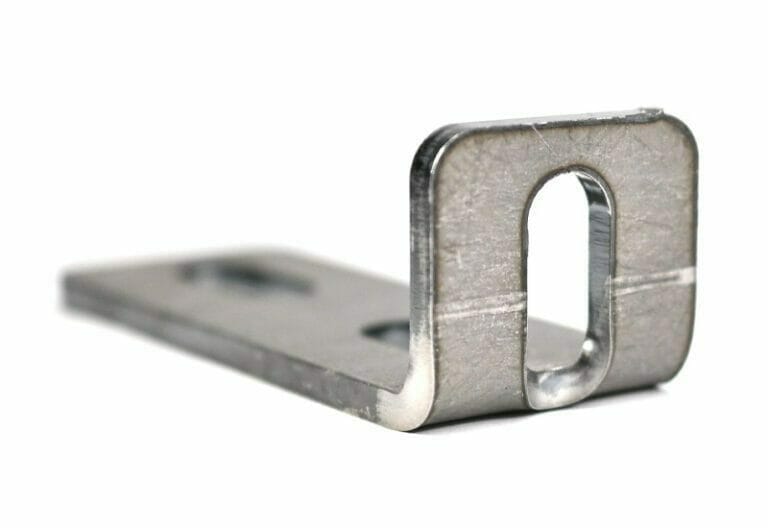
It’s important to know how to design for laser cutting and sheet metal bending together so each aspect of your design functions the way you need it to. Watch the video and follow along with the guide below to learn how to effectively plan laser cut features around bend lines to avoid bulging and distortion.
Video Guide to Planning Features Around Bend Lines
Components of a CNC Brake
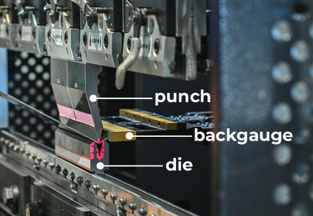
Let’s go over a couple components that are in the CNC brake to better understand how bending can affect your design. A CNC brake has three main components: the punch, the die, and the backgauge.
The backgauge gives you a flat surface to put the material up against that not only orients the part at the needed angle, but also at the needed depth with respect to the punch and the centerline of your bend. This is why each bend line needs a parallel edge. We have more information about this in our guidelines: Odd Flange Shapes
Next we have a punch that sits above the part and the die that sits below it. As the part sits on this die, the punch will come down and make contact with the surface of the part, forcing it down into the die. There are a lot of different flavors of dies in the form of different angles and widths in which they contact the part.
Contact Points Between the Material and the Brake
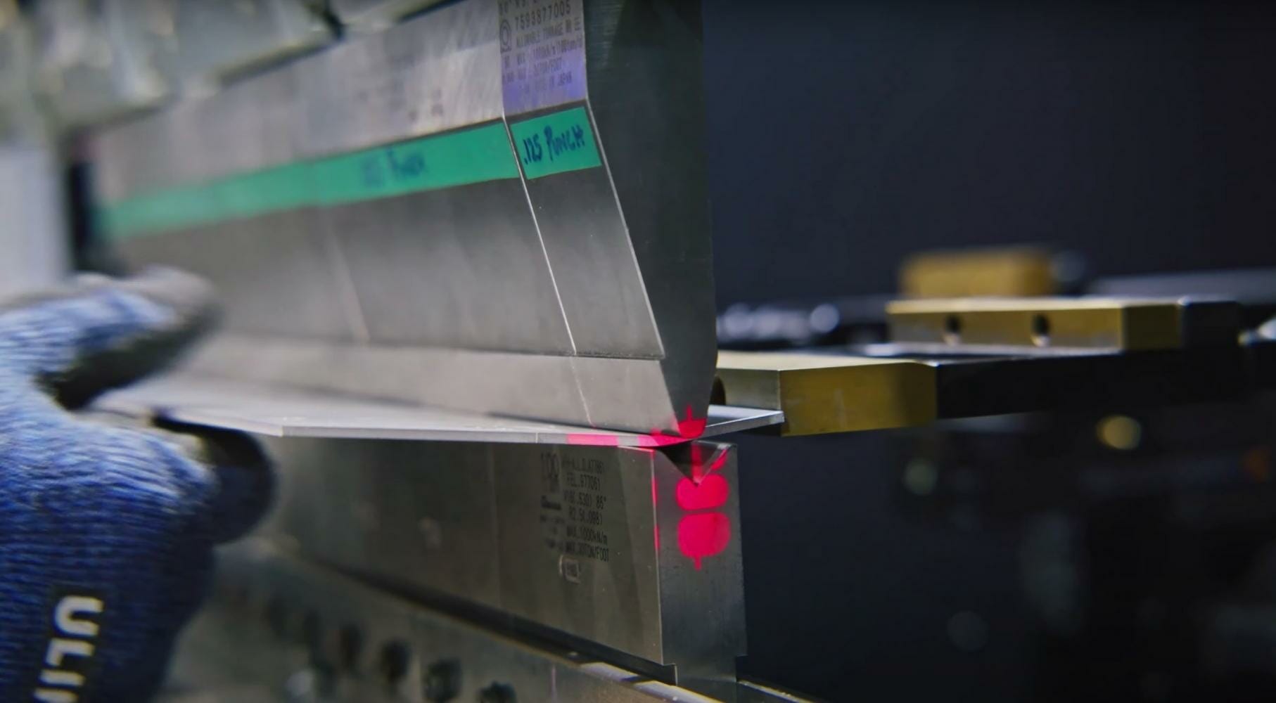
There are three main contact points not including the backgauge. There is one contact point at the apex of each side of the die, and one where the point of the punch meets the material. It’s important to note that when you receive your parts that are being bent, you’re going to see a witness mark which are often referred to as die marks. These are created by the contact between the material and the punch and die.
As the punch comes down and presses the material in, the part is going to start bending. The material will fold into the pocket of the punch, and as the punch comes down and forces into the material, it’s not actually going to push the material all the way down to the bottom of the die. There will be a small radius at the apex of the bend.
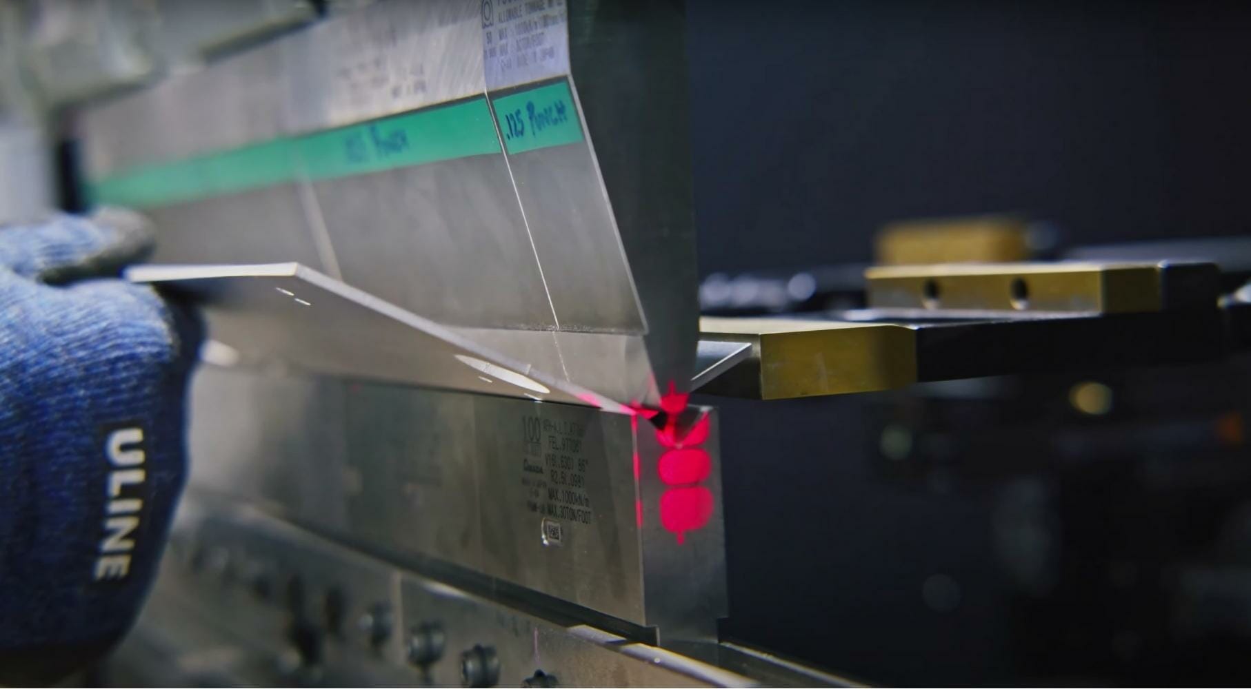
Here at SendCutSend, we don’t do coining. Coining is the operation in which the punch shoves the material fully into the die, applying pressure and forming a bend. If the material doesn’t go to the bottom of the die and there is a gap, it’s called air bending and that’s what we do in our shop.
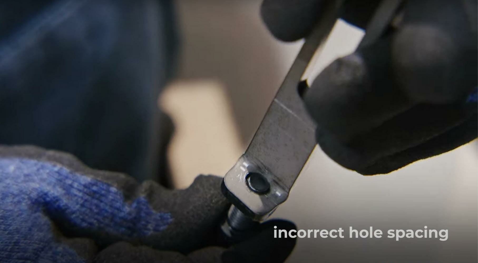
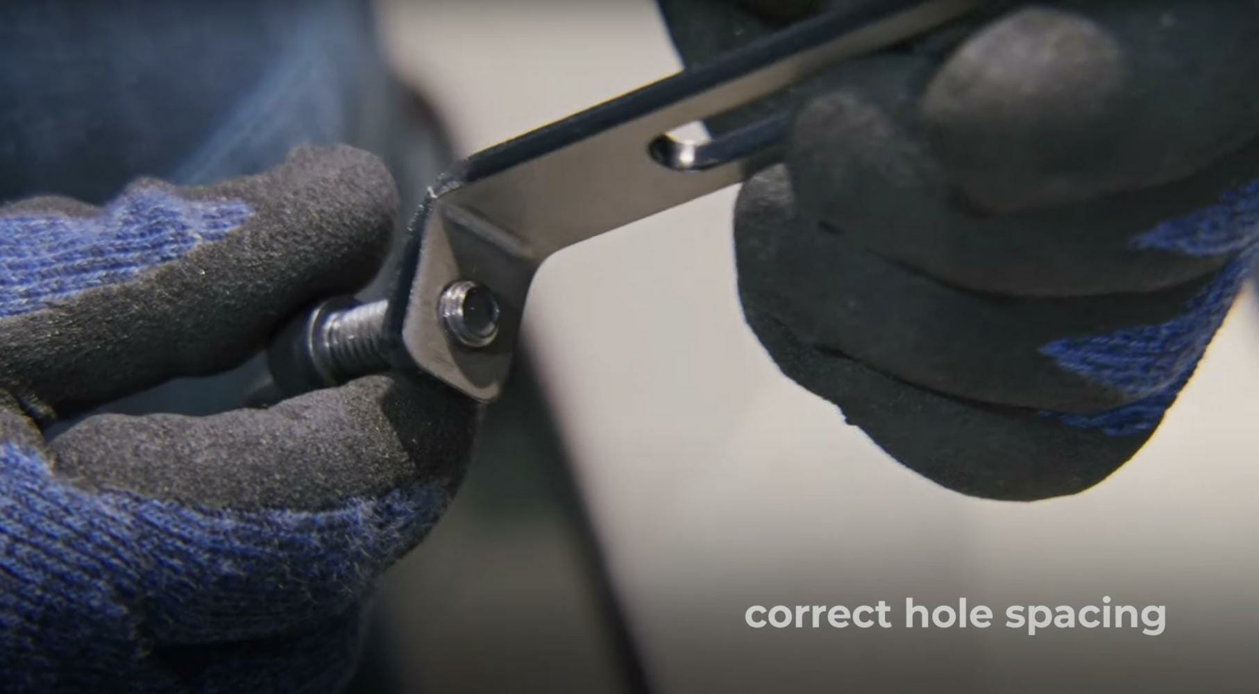
Anything that falls in between those contact points within the die is liable to see some kind of distortion during the bending process. If you have a hole inside that area, it is going to be affected by distortion and not work exactly how you wanted it to.
If you go to our design considerations for your chosen material, you’ll see that we’ve listed the die width we’ll use for bending that material, as well as all other information you’ll need to ensure that you have placed features far enough away from the bend line.
For example, you can navigate to the 5052 aluminum page to find the die width for the material thickness you need under Bending Specifications.
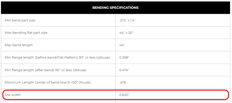
If you divide the die width by 2, you’ll find the minimum distance that cut features need to be placed away from the bend line to avoid distortion.

We have more info about how to avoid feature distortion from bending in our Die Line Considerations.
Designing Bend Relief Notches
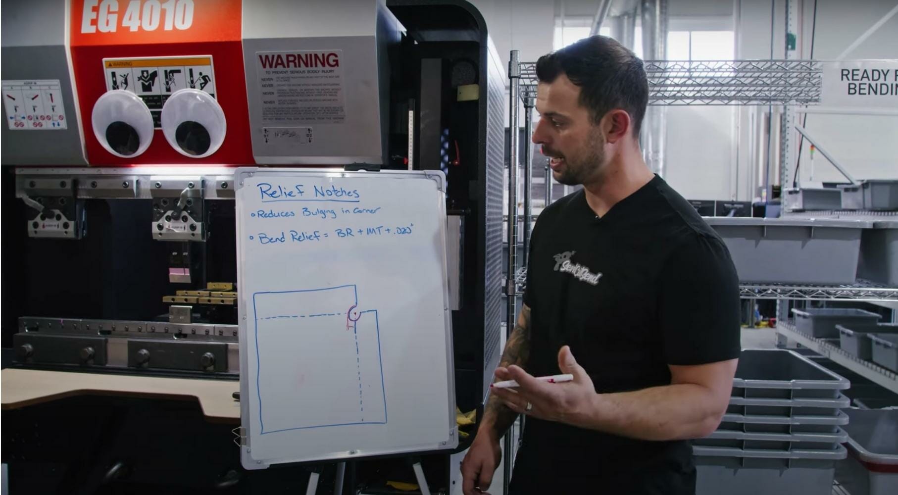
“Relief notches” are a feature that you can put into the design that will help prevent distortion during the bending process. If you have a bent part that has a base flange and two return flanges bent at 90-degrees relative to each other, you will see bulging in the corner at the intersection of the two bend lines if you don’t put a bend relief in. This is because as the material stretches during bending, it is forced to move and push into a bulged point.
The quick and easy fix is to cut a circle that is centered at that axis between the two bend lines. That circle’s radius, or the bend relief, is going to be the sum of the bend radius (found on the material page and bending calculator), the thickness of the material that you’re using, and 0.020”. Use that total to add a cut circle into your design prior to uploading it for quoting. Now as the flanges are bent, you’ll be left with a nice edge without bulging or distortion.
SendCutSend’s Bending Series
This video and guide concludes our bending series which includes information on everything from bending terminology to calculating bend allowance. All videos are in a playlist on our YouTube channel so you can go back through to pick up on all the information you need to create a successful bent part. We’ve created guides and transcripts for each one as well, which you can find on our blog through the links below.
If you’ve already watched our bending series, read through the bending guidelines, and are ready to get going on your CNC bent sheet metal parts, just upload your file to our website and get instant pricing!


