1. Upload a file format we accept
To set up part files for bending, plan to upload a file format we accept.
Currently we accept STEP and STP format 3D files, and DXF, DWG, EPS, or AI format 2D vector files.
2D files should only show your part’s cut geometry and bend location lines.
If you design your parts in non-CAD software (Adobe Illustrator), please send us the original (native) .ai file. We’ll take care of the conversion on our end. While we accept .AI and .EPS files, it’s critical that your bend lines are parallel when uploaded from these software or the file will delay our process. See our in-depth guide on setting up parts for bending in Adobe Illustrator for more detail.
For the fastest turnaround on your order, we recommend setting up your parts for bending in a CAD software.
If you’re using the Parts Builder, see our FAQ on how to add bend lines in the Parts Builder.
2. For 3D files, model your formed sheet metal part
3D STEP/STP files should have your bends set up as sheet metal parts using our material bending specifications.
- Using Autodesk Fusion or SolidWorks? Download our gauge tables to easily apply the latest specs!
Model your bent flanges in your file. When you upload your STEP file to our website, the flanges and their definitions should be detected, but review the bending service configuration to ensure all definitions are correct.
Learn more about STEP/STP file bend configuration.
3. For 2D files, use the correct bend line type
Reference this chart to know what kind of lines are needed to indicate the bends in your part. Each bend line should mark the center of each bend. The bend line type changes based on what software you use:
| Software | Format | Bend line |
| Adobe Illustrator | .ai | Solid, separate color from cut lines |
| AutoCAD | .dxf | Dashed line (not hidden) |
| CorelDraw | .eps | Solid, separate color from cut lines |
| Fusion | .dxf | Solid line (default)* |
| Inkscape | .eps | Solid, separate color from cut lines |
| SolidWorks | .dxf | Dashed line (not hidden) |
| QCAD | .dxf | Dashed line |
*For Fusion you will need to apply a thickness, convert to sheet metal, create a flat pattern, export .dxf, then convert spline to a polyline. This will result in 3 solid lines to export. The center is automatically detected in the SendCutSend app for bending. See How To Export to DXF in Autodesk Fusion for more information.
4. Check your design with our bending calculator
Use our bending calculator to ensure that your formed flanges will have the desired final dimensions. Set up your design with our specifications for the material you choose. In programs like Autodesk Fusion, this means your part will need to be set up using sheet metal rules that use our K factor and bend radius specifications.
Please note: we do not bend parts with custom radiuses. Find the bend radius for each material thickness on our bending calculator page or in the Material Details for the chosen material.
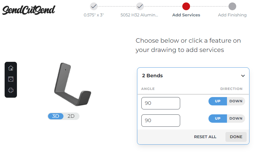
5. Don’t use notes; simply configure parts in our app!
Do not leave notes in your file indicating the bend angle. During the ordering process, you will be able to specify the bend angle when you add the bending service to your parts. Learn more about why we don’t require callouts or notes!

Whether you upload a 2D or 3D format file, you will be able to view your bends in a 3D model during the checkout process to make sure the angles and flange orientations are correct.
Ready, set, bend!
Setting up part design files for bending can be a complicated process, so review all of our bending guidelines to make sure your parts fit within our requirements for bending!
