When preparing a design for laser cutting and bending with SendCutSend, there are a lot of factors to consider – bend deduction, material stiffness, and bend reliefs to name a few! In this article, we’ll show you how to preflight the flat, 2D vector file of your design for bending services using QCAD.
QCAD is a free, open source 2D program we frequently recommend for file review and revision. If you’re not familiar with QCAD, we have a thorough guide with instructions on how to download the installer, set up your workspace, and learn some of QCAD’s most useful commands.
After you place an order, SendCutSend’s applications team will review your design to confirm that it meets SendCutSend’s guidelines and should form successfully. If any issues are found, your order will be put on hold and we’ll contact you with any questions or concerns. This can add one or more business days to your order’s overall lead time.
If you’re counting on SendCutSend to help grow your business, we understand time is of the essence! Double checking our guidance here should see your products moving smoothly into production whether you’re serving just a few customers, or thousands.
Creating Your Flat File
Your design may have been created in a 3D program like Autodesk Fusion or SolidWorks, or you may have drawn it flat in a 2D program like QCAD or Adobe Illustrator.
If you designed your part in a 3D program, we have tutorials on exporting a flat file. You’re welcome to export a STEP file instead – just make sure it meets our 3D file guidelines!
If you drew your flat pattern in Adobe Illustrator, we have guidance on preparing Illustrator files for our bending services. However, while we can bend parts originating from Illustrator files, we strongly recommend switching to a true CAD program like Autodesk Fusion or QCAD for designing parts that require bending or hole operations.
This is because CAD programs are optimized for drawing the exact geometry needed for these technical operations, while Illustrator is not. Adobe Illustrator is best suited for artistic, decorative designs that don’t require a high level of precision.
If you drew your flat pattern in QCAD, excellent! QCAD allows you to save DXFs natively, so preflighting the file can be a natural final step in your design process.
Review Bending Calculator
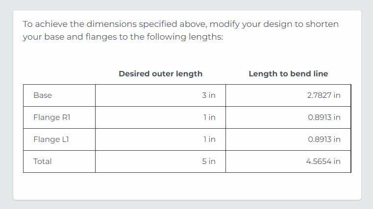
We strongly recommend using our Sheet Metal Bending Calculator to check that your flat pattern’s dimensions will result in the formed dimensions you need – especially if you designed your part in 2D.
When you select your material of choice at the top and enter your desired base and flange dimensions (after bending,) the calculator will take the internal radius of each bend, the bend deduction, and the K factor into account when it provides the flat dimensions you need.
The bend radius is set for each material thickness and cannot be changed upon request.
If you design your parts in a 3D program, make sure your sheet metal rules are set up using SendCutSend’s bend radius and K factor specifications.
Preliminary Check
Once you have a flat, 2D vector file (DXF or DWG format) prepared, open it in QCAD and check to make sure your unit of measurement is correct.
Go over the general How to Preflight Your Designs Using QCAD guide and its checklist to confirm that your file is cut-ready.
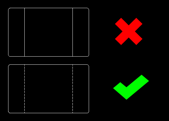
Then, make sure your cut paths are set to the Continuous line type, and your bend location paths are set to the Dashed line type.
You can do this by selecting the paths using the cursor (QQ,) and then updating the Linetype in the drop-down menu in the Property Editor (GP.)
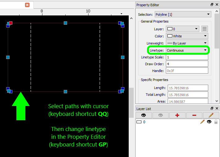
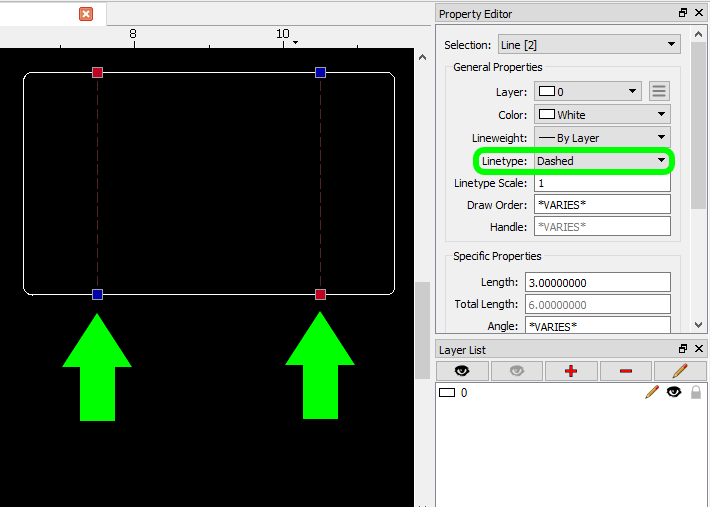
This will ensure that SendCutSend’s application recognizes your bend location lines correctly and allows you to configure each bend operation before you checkout.
Please note: in this guide, example designs will have different colors for different line types and cut geometry, but this is only to help make the examples clearer.
For designs you’re submitting in an order, all of your paths can be the same color.
Design Considerations
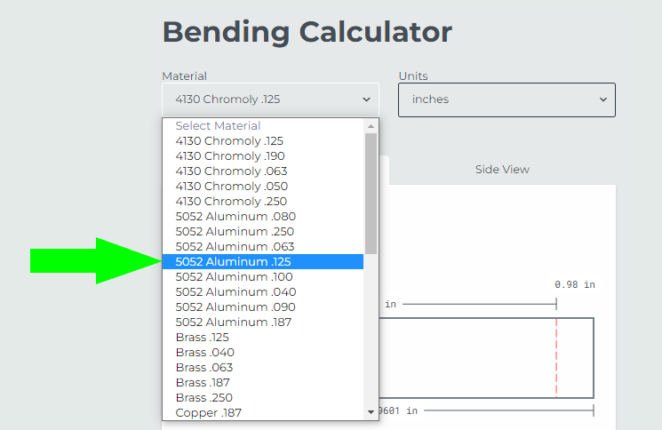
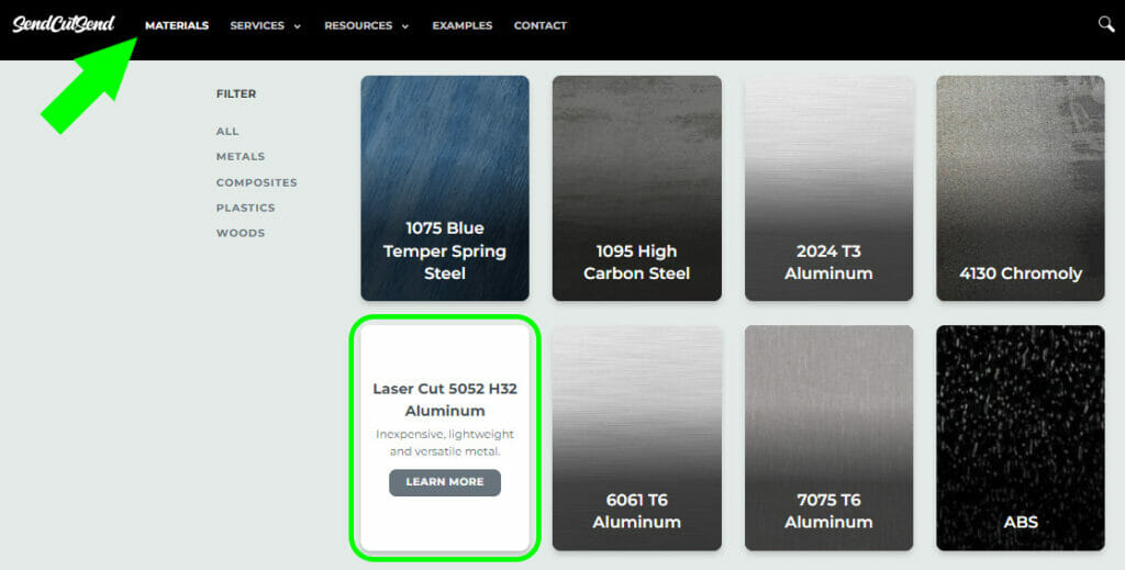
Once your file is ready to begin bending preflight, open SendCutSend’s Materials page, and select the material you need for the part you’ve designed.
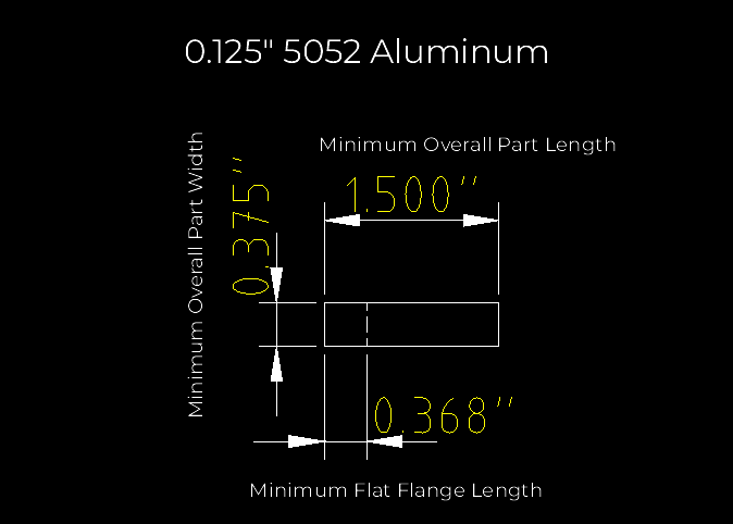
For this guide, we’ll use 0.125” 5052 H32 aluminum.
Once you’ve opened the 5052 aluminum page, scroll down to Material Details and choose your desired material thickness via the tabs on the left.
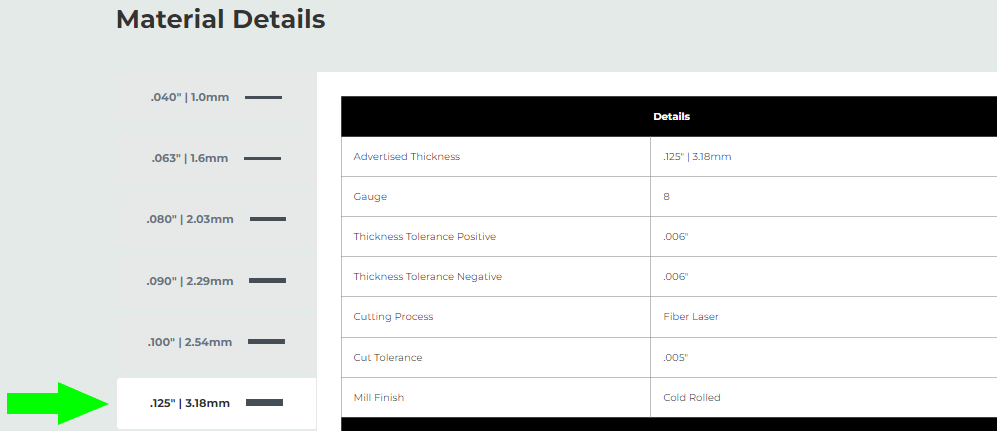
Then scroll down to the Design Considerations. The Design Considerations section for each material thickness is where you can find critical specifications for all available operations in one place.
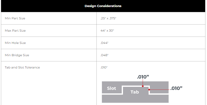
Scroll down to find the bending considerations.
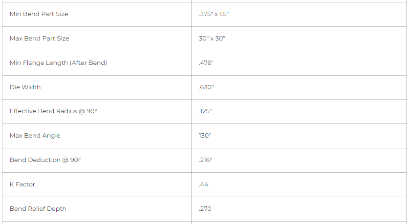
We’ll refer to these critical specifications often throughout the guide.
Overall Dimensions
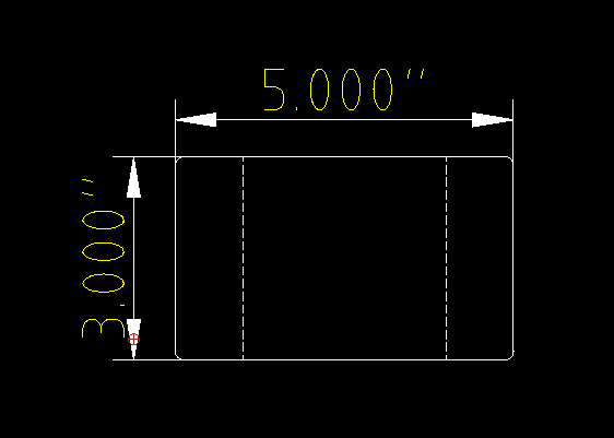
Make sure the overall dimensions for the flat part are no smaller than the Min Bend Part Size, and no larger than the Max Bend Part Size.
You can use the following tools in QCAD to take the measurements:
- Aligned Dimension – freely measure between two points (keyboard shortcut DA)
- Horizontal Dimension – angle fixed at 0° (keyboard shortcut DH)
- Vertical Dimension – angle fixed at 90° (keyboard shortcut DV)
Minimum Flange Dimensions
Minimum Flange Length
Minimum Overall Dimension
Check that each of your flanges is at least the Min Flange Length (After Bend.)
This number represents the minimum overall dimension for the finished flange length. Most 3D CAD programs will allow you to adjust your design using this value.
Minimum Flat Flange Length
When measuring on a flat pattern, you can find the minimum flat flange length for your material of choice on the material info page under Material Details – Min Flange Length (Before Bend/Flat Pattern).
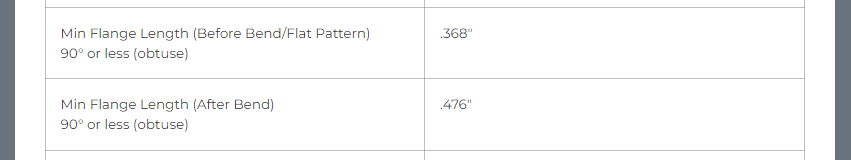
Knowing the minimum flat (before the bend) flange length is helpful if you are working primarily in 2D.
You’ll want to make sure you have at least the minimum flat flange length of material on both sides of the bend line so our tooling has enough ‘grip’ on the material to perform the operation.
If, on your flat pattern, your flange is the minimum flat flange length, after the flange is bent, it will be the minimum overall dimension or Min Flange Length (After Bend.)
Here, we used the Aligned Dimension tool (keyboard shortcut DA) to take the flange measurements, with QCAD’s Auto Snap settings set to snap to center points on paths.
We have guidance here about customizing your preferences in QCAD similarly.

Minimum Flange Width
Minimum flange width is dictated by the minimum overall part width that can be bent in a specific material and thickness.
Please note, if your flange is the minimum overall part width, we need the full flat surface area.
If your flange needs radiused corners, please widen your flange or overall part width to ensure the minimum flat surface area is available to brace against our press brake’s backstop and execute the bend accurately. To see why we need this, check out how our bending operations are performed in this video.
Flange Clearance at Corners
If your design has perpendicular flanges that meet in a corner, like a box, you’ll want to ensure there’s enough clearance so the flanges don’t collide, preventing the operations from being completed.
Reference our bending specification table
There’s some math that goes into calculating corner clearance, so we’ve made it easy!
Reference the Min Corner Relief Distance from Bend Line spec in our handy bending specification table. Check it before your next project to ensure you’re using the latest data, and follow the steps below to confirm there’s sufficient clearance between perpendicular corner flanges.
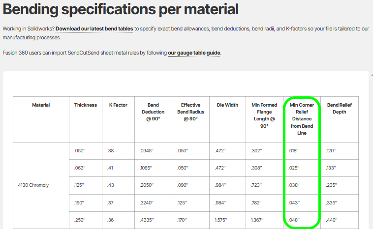
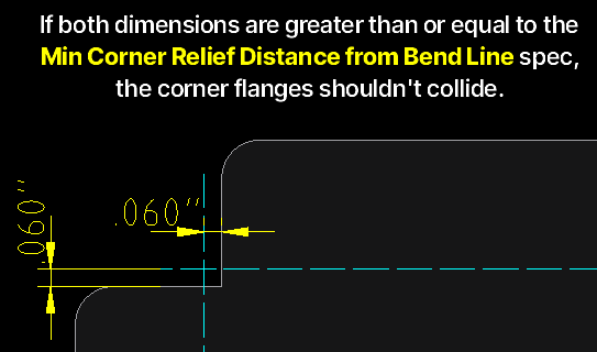
Checking corner flange clearance with the Min Corner Relief Distance from Bend Line specification
1. Extend the bend lines for each corner flange out past the edge of the flanges.
2. Then, measure the distance between each bend line and the adjacent flange edge.
3. If the distance between the corner flanges’ extended bend line and the other flange’s edge is equal to or greater than the Min Corner Relief Distance from Bend Line specification for your chosen material thickness, the flanges shouldn’t collide.
Pro tip: our Min Corner Relief Distance from Bend Line spec is calculated as follows:
Material Thickness – (Bend Deduction @ 90°/2) + 0.015”
You can find the bend deduction for all of our bendable materials on our Bending Calculator page or in the Material Catalog.
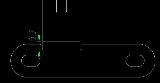
Bend Reliefs
Although the above design now has sufficient flange clearance, it is lacking in relief for the bends. The material is likely to tear or crumple in the corners.
We have a thorough guide on how to measure bend reliefs, but we’ll recap it here and focus on how to measure bend reliefs on a 2D flat pattern.
You can think of bend relief as space for the bend operation to occur without tearing the material. You can create adequate space for the bend to occur by either shifting the bend line away from the base of the part, or adding slots or notches into the part to prevent tearing material that you don’t intend to be bent.

The depth of your relief should be at least the material thickness + the bend radius + .020” (0.5mm) measured from the bend line or center of the bend.
Fortunately, we’ve made it easy for you to measure the bend relief on a flat pattern!
The Bend Relief Depth value listed for each thickness in the material info pages should be measured from the bend line, and the notch should extend to at least the recommended relief depth.
If the profile of your part is a polyline, you can select it using the cursor tool (QQ) and use the Explode command (keyboard shortcut XP) to explode it into individual lines.
Then, you can use QCAD’s Line Tools (keyboard shortcut WL) to draw your notches, and the cursor tool to readjust the paths that make up your part’s profile.
If you’d like to draw an obround notch, QCAD’s Arc Tools (keyboard shortcut WA) make it easy to add an arc to the end of your notch.
Please note, for polycarbonate parts we require that bend reliefs meet the minimum required depth and are a square shape.
To ensure there are no disconnected paths when you are finished drawing your notches, you can select a path on your part’s profile and press OC to Create a Polyline From Selection. If the whole part profile becomes a single polyline, you have no disconnected paths.
Corner Reliefs
For corner reliefs, the principles are exactly the same; they just happen to intersect!
Our bend relief guide shows multiple examples of corner relief styles you can draw.

Parallel Edges
Each flange needs a parallel edge for our press brake’s backstop to gauge off of. This enables us to bend parts accurately and within our tolerances.
There’s a section in our general QCAD design preflight guide that instructs how to use the Angular Dimension tool (keyboard shortcut DN) to confirm if a flange is parallel to its bend location line.
Odd Flange Shapes
If your design needs an odd flange shape, we have a video that explains how to revise your design so we’ll be able to bend it.
You will need to add a parallel surface that you’ll remove when the part gets to you.
The tabs will need to be at least the Min Bridge Size wide.

Die Width Considerations
We have information in our bending guidelines and FAQs about witness marks left by our press brake’s tooling, as well as an in-depth guide explaining how to plan cut features around bend lines.
Here are some examples of typical witness marks from the press brake’s die:
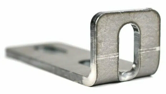
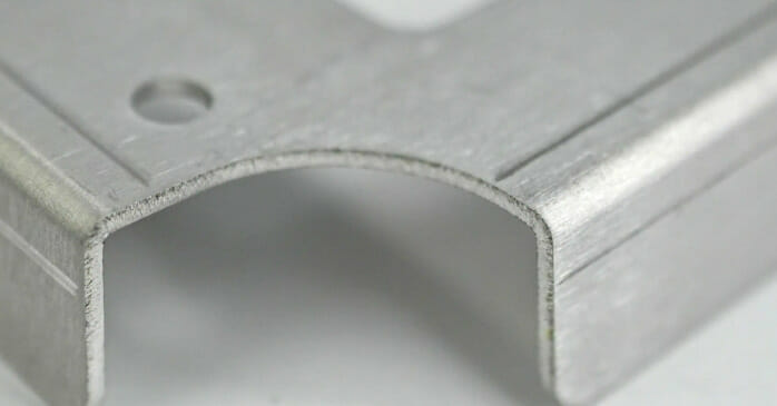
If cut features fall within the die width of our press brake, they can be distorted (as seen in the left photo above.)
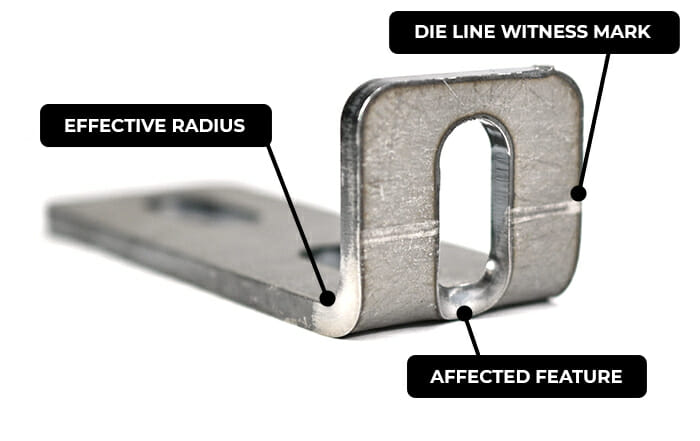
To avoid this, make sure any cut features are outside the die line, or Die Width/2 away from the bend location line.
We have detailed instructions on how to use the Offset with Distance tool (OF) to check this in our general QCAD preflight guide.
Tapped Holes
At SendCutSend, parts are tapped before they are bent. Make sure any holes you need tapped are outside the die lines to avoid distortion, which will render the threads unusable.
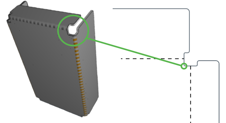
Countersunk Holes
If your design includes holes that will be countersunk, you’ll need to take an extra step to check and see if your countersunk hole’s major will fall within the die lines. Parts will be countersunk before they are bent, so you can expect results like this if majors are too close to your bends:

Per our countersinking guidelines, any holes to be countersunk should be drawn with the minor diameter of the countersink size you need.

Therefore, you’ll need to check the die line width against the major diameter that will be present after your holes are countersunk.
To do this, mark the die lines by entering the Die Width value from the Design Considerations into the Distance field of the Offset with Distance tool (OF) divided by 2.
Hover your cursor over the bend location lines to mark each side of the die on your flat pattern.
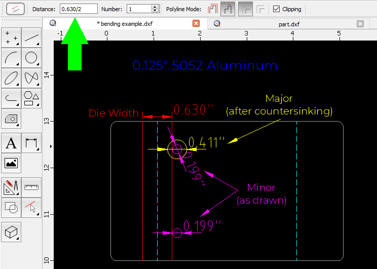
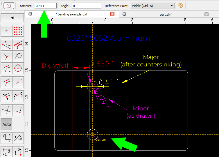
Then, use the Center, Diameter circle tool (keyboard shortcut CA) to create a circle that is the diameter of the countersink’s major.
Place the major circle on top of the minor circle to see if the major overlaps the die line and will be distorted.
Hardware Holes
Hardware is installed after parts are bent. It’s important to ensure the hardware mount holes are far enough away from bends and that flanges for 4-sided box bends are short enough to allow access to the installation points.
Important bending specifications in the Hardware Catalog
J = Bend allowance area (find with the Bending Calculator)
N = Minimum distance from center of hole to edge of bend allowance area (J)

You can confirm the minimum distance required for your chosen material by finding the Minimum distance hole C/L to edge (K) or bend (N) value in the Hardware Catalog.
We have detailed guidance on hardware-to-bend proximity in our Hardware Guidelines. You can use the Aligned Dimension tool (keyboard shortcut DA) to measure from the center of the hardware mount hole to the edge of the bend allowance area.
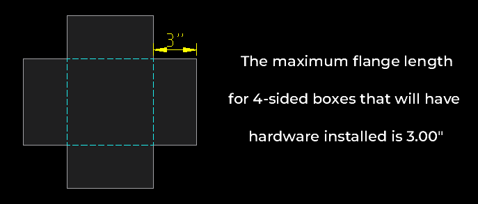
For hardware mount holes located on flanges, you can confirm the maximum 4 sided box flange height by finding the Max 4 sided box flange height (hardware) value in the material’s Design Considerations.
Please be sure to review SendCutSend’s hardware installation guidelines and hardware catalog while designing your parts to confirm that all critical specifications are met!
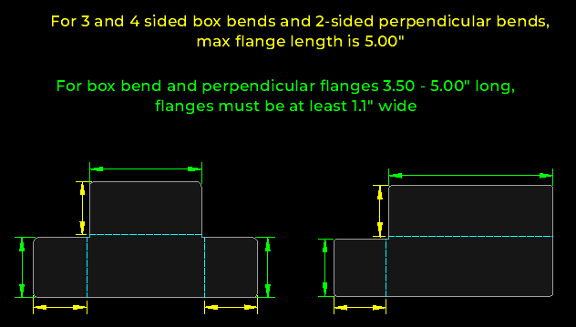
Box Bends and Perpendicular Bends
We have specific flange length and width requirements for perpendicular flanges that meet at a corner. Learn more in our box bend writeup!
U-Channels
Per our bending design guidelines, we generally require a base-to-flange ratio of 2:1 in sheet metal for u-channel or c-channel bends. However, there can be some flexibility depending on the material thickness required – take a look at our channel bends writeup for specific guidance!

On your flat pattern, you can use whichever of the dimension tools you prefer in QCAD to check this:
- Aligned Dimension – measure between two points (keyboard shortcut DA)
- Horizontal Dimension – angle fixed at 0° (keyboard shortcut DH)
- Vertical Dimension – angle fixed at 90° (keyboard shortcut DV)
We require a 3:1 ratio for polycarbonate parts.

Let’s Get Formable!
With this guide in hand, you’re on your way to successful production runs and great-looking bent parts. If you have any questions, feel free to check out our bending FAQs and YouTube channel, which has a ton of informative bending videos! When your design is ready, upload it to our website for an instant pricing.
