*While we accept .AI and .EPS files, it’s critical that your bend lines are parallel when uploaded from Illustrator or the file will delay our process. For the fastest turnaround on your order, we recommend designing your parts in a CAD software such as Fusion, AutoCAD, or SolidWorks. If you design your parts in Adobe Illustrator, please send us the original (native) .ai format file. We’ll take care of the conversion on our end.
In this tutorial, we’ll look at how to set up your Adobe Illustrator file for metal bending with SendCutSend.
Before you start
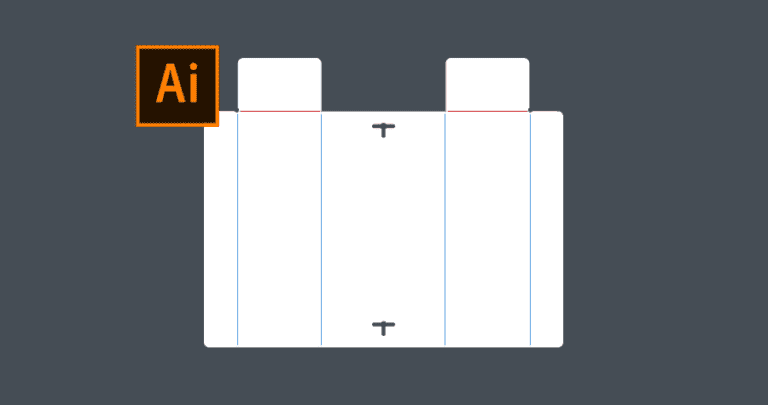
To start, download the demo file here and open it in Adobe Illustrator. I’ve designed this laptop holder that is bent from sheet metal. You’ll see that I’ve finished the flat pattern with all flanges included. It’s important to note the minimum and maximum flange length. Each flange length must meet the minimum specification for the material, which can be found on the individual material pages.
1. Create bend lines
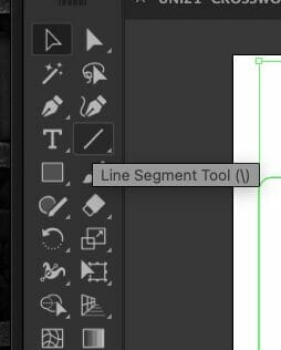
We’ll need to create lines at each flange that needs to be bent. Zoom in on one flange and activate the Line Segment tool from the Tool Panel. You’ll find it nested with the Rectangle tool by clicking and holding on the rectangle icon. We can then create straight lines for each flange that requires bending.
Switch to the “Selection Tool” with the shortcut letter “V” to manipulate the length and position of the lines. You can also hold the shift key which will help you extend the lines without reorienting them.
To quickly recreate additional lines of the same size, hold down “Option” on Mac or “Alt” on Windows, in addition to the Shift key. This will allow you to duplicate the line segments while keeping them on the same axis.
2. Indicate your lines
Before uploading to SendCutSend, each bend line will need to be indicated using a single color. You’ll want to send all bend lines to a color different than the rest of your design. The color of the line does not matter. Please do not use dashed lines.
The direction of each bend does not matter, you’ll be able to design the bend direction while getting a quote on our website.
The Bend lines should not be placed on a separate layer in Illustrator. The entire flat pattern, including the bend lines, should be on a single layer.
In the Layers Panel you can select everything and drag it to the main layer. Then drag any unwanted layers to the trash icon.
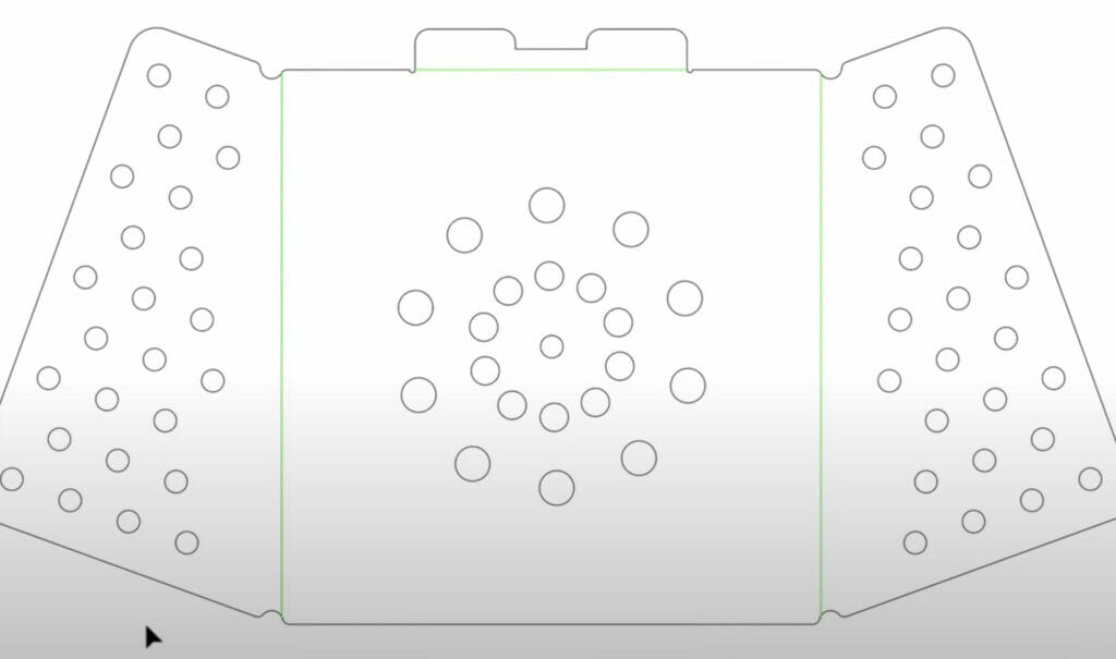
3. Move lines away from the base
Lastly, I also want to move the bend lines away from the base to help avoid tearing in the corners. In Illustrator, you can precisely move lines by first selecting the desired lines and shift-click multiple lines to move more than one at the same time. You can then type out exact dimensions in the Transform section of the Properties pane.
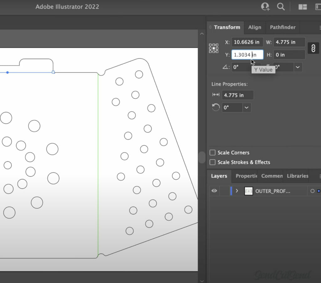
For example, I’d like to move the top two bend lines up .13 inches. Adobe Illustrator allows us to type out equations directly in the input fields. I can type out the minus symbol, followed by .13 inches, and the enter key. If you’re following along, you’ll notice how the lines precisely moved based on values we input. This approach makes it much easier to be precise when compared to manually dragging lines around.
Keep in mind that you can use the addition symbol to move the geometry in the other direction. You may also find that you need to resize the length of your line if its new location requires a different length. Double-check that the length of each line is not sticking past the outer contour or crossing any unwanted geometry.
Repeat this process for the remaining bend lines.
4. Apply Bend Deduction
Once the bend lines are in place, we need to consider the Bend Deduction.
The overall length of sheet metal becomes stretched out when the sheet metal parts are bent. Bend Deduction is used to counteract material stretch caused by forming. Bend Deduction is unique to each material type, thickness, and bend angle, so we recommend using our Bending Calculator, which makes it easy to factor in bend deduction!
In the Bending Calculator, start by selecting the desired material. Then, input the desired finished dimensions to find the required flat dimensions.
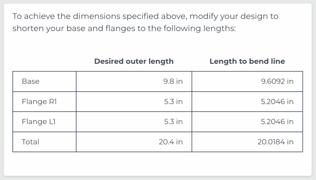
Back in Adobe Illustrator, we can copy and paste the total modified length to the width of our overall contour. You will then want to repeat the process per each direction the part includes bending.
Once complete, your design is all set and ready for uploading! Be sure to check out our other video on Exporting from Adobe Illustrator for Laser Cutting and then reference our checklist to double-check that your file meets our latest requirements.
