Most of us wish a fancy 3D scanner will show up at our door, but the good news is you can still build some high-quality parts that you can order from SendCutSend using leftover boxes, scissors, tape and some free software. Also known as Cardboard Aided Design and Computer Aided Design. In the end we’ll have a project that is solid, professional looking and pretty low effort.
Let’s look at a race car rear wing project. We’ll go through the project in three steps:
- Supplies, design and approach.
- Prototyping a template and considerations to keep in mind
- Getting the prototype into the digital realm.
Supplies, Design, and Approach in Cardboard Aided Design
If you are reading this article chances are you’ve heard of both CAD (Computer Aided Design) as well as CAD (Cardboard Aided Design). The truth is that for most projects that the garage warrior will build, careful effort with some cardboard can result in flat parts that can be laser cut and assembled into very usable parts.
The first step is to acquire cardboard and a good set of cutting tools. High-quality scissors and sharp razor blades will ensure clean, precise cuts. A crisp template will make the subsequent steps much easier. Measuring tools like rulers, tape measures, and angle gauges are also necessary, as are markers, pencils, and masking tape.
The ideal type of cardboard depends on the project. For larger parts, corrugated cardboard from a packing box offers stiffness, which aids in positioning the template. However, it tends to be less precise when cut. For smaller projects, poster board is more suitable due to its ability to be folded and cut crisply, resulting in a more accurate prototype. If the template requires additional rigidity, a second layer of cardboard can be taped perpendicular to the axis where bending might occur. This second layer helps simulate the thickness of the final part, aiding in understanding clearances and fitment. If the template cannot be positioned without bending, it likely won’t function as intended and may require a redesign. All cardboard layers should be cut cleanly and evenly to avoid dimensional confusion. Mixing cardboard types is acceptable. Creativity with tape and marking strategies is encouraged. The information recorded on the template, such as hole dimensions, distances, and angles, will prove invaluable when transitioning to the digital realm.
Remember: the more time invested in creating an accurate cardboard template, the better the final product will be. This minimizes the need for modifications or reordering parts after changes are made.
Engineering the cardboard
Let’s look at the race car wing project
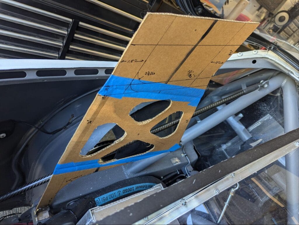
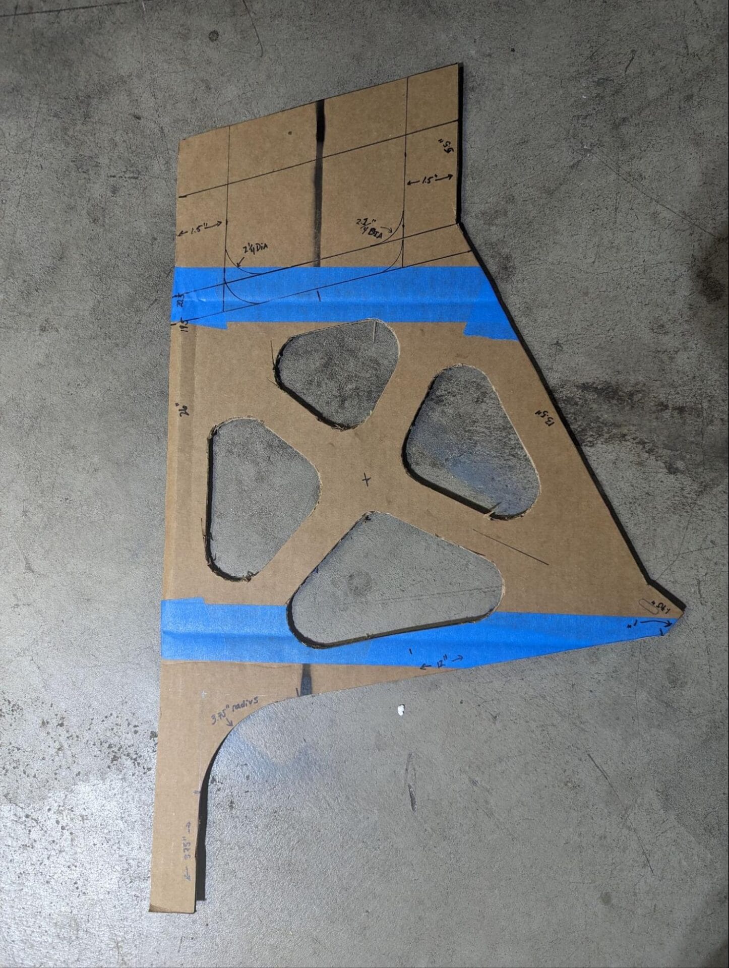
In the above photo the lower part of the wing stanchion that will connect the chassis to the wing mount itself is shown as a cardboard template in position.
The first thing to be considered are the forces that this part will see in service, the materials available to build the part and the complexity of construction. This part will see both compression and tension in service.
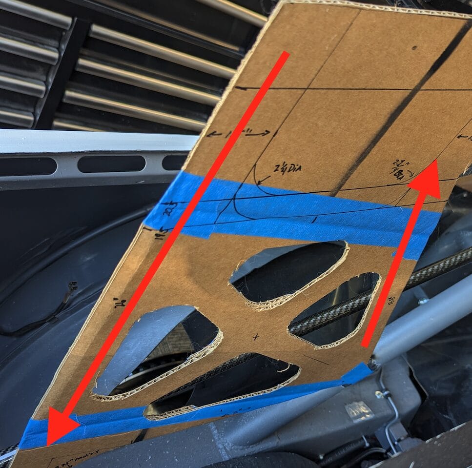
The rearward mount point will experience compressional loading, while the front mounting point will experience tension. Since the part is being fabricated from flat sheet metal, it is important to understand the capabilities of the available materials.
Metals are generally isotropic, meaning they exhibit equal strength in tension and compression. However, engineering for buckling under compression is typically more challenging and often necessitates additional material, especially as dimensions increase. Therefore, selecting a material and thickness that can withstand the anticipated loads, with a safety factor, is crucial. In this instance, 6061 T6 Aluminum from SendCutSend met the weight, strength, and cost criteria. While incorporating a back strap to assist with compression is feasible using laser-cut flat parts and could result in an overall lighter component, this will be explored in a future discussion.
Another practical engineering consideration is adjustability. Without a comprehensive computer-based model offering precision to the thousandth of an inch, it is inevitable that some parts will require adjustment during assembly. Moreover, when using cardboard templates, the highest achievable accuracy is realistically around a sixteenth of an inch (or a few millimeters).
Consequently, it is beneficial to design some adjustability into the part during template construction. For instance, incorporating slots instead of precisely dimensioned holes can provide flexibility for part positioning. However, if the final attachment method involves clamping via bolts, it is essential to ensure that the hardware is capable of preventing slippage during operation. While these slots or oversized holes can be drawn on the template and modeled in software, they should be sufficiently close to the desired final dimensions to avoid compromising the part’s strength through excessive adjustment later.
Alternatively, leaving the template blank and drilling or slotting the part after it is fabricated from the final material can offer a more robust solution to address this uncertainty.
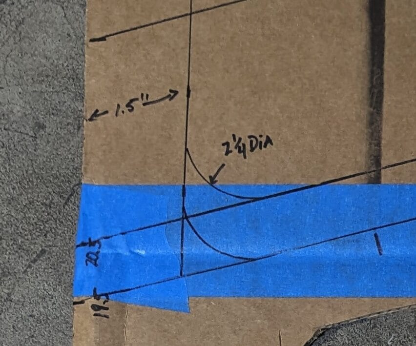
As the template is gradually refined (and occasionally restarted—it happens to all of us), users should not hesitate to include ample information on it. Notes on left/right orientation, driver side, distances to known references, known angles, and other relevant details will prove helpful when transitioning to the computer.
IMPORTANT: One particular and very important factor must be recorded on the template. A single feature needs to be designated as the reference measurement to construct a digital replica in the computer. Best practice dictates making this reference a straight edge of known length. While a radius or diameter can be used, these features are challenging to calibrate in practice and should only be considered as a last resort.
From Paper to Digital
Now that a template has been created that is accurate to the best of one’s abilities, and a reference measurement has been marked clearly, the transition from cardboard to CAD can begin. This is accomplished by importing a picture of the template into CAD as a reference canvas for modeling the part.
The user should take their phone and template to a suitable location for capturing a picture of the cardboard. This step is more important than it may initially seem, and three key factors must be addressed to improve accuracy.
- Ensure a neutral, light-colored background, such as a concrete floor or driveway. Darker or complex backgrounds can hinder template visibility in CAD software.
- Use excellent lighting with multiple light sources to eliminate shadows from the photographer’s body and phone, helping define edges for tracing lines and curves. A clean, crisp template further enhances this process.
- Take the photo from directly overhead, as high as possible. Utilize all features of modern phone cameras and consider using a step ladder or stool for added height. Increased height and centered positioning minimize parallax—the visual distortion of an object’s perceived length due to viewing angle. Parallax in the photo can lead to a mismatch between the CAD canvas and the model. While not catastrophic if the template has ample reference measurements and angles, it serves as a valuable sanity check to ensure model accuracy.
Importing Your Sketch Into a CAD Software
The next step in the process involves importing the picture into the user’s preferred CAD software. At this point if you do not have access to a CAD software or simply don’t want to deal with you, you could utilize SendCutSend’s Design Services.
Through SendCutSend’s Design Services you can send your sketch or cardboard template to their team and they will create a CAD file for you. There’s a nominal fee, but it’s a worth alternative if you don’t have CAD.
Back to importing your picture into a CAD software. Many amateurs, including the author, use Autodesk Fusion, free software for individual hobbyists that is compatible with both Mac and Windows operating systems. While this demonstration won’t delve into software installation or project setup, numerous tutorials are available to guide users through these initial steps.
The subsequent task is to utilize the canvas function within Autodesk Fusion to integrate the captured photo into the project.
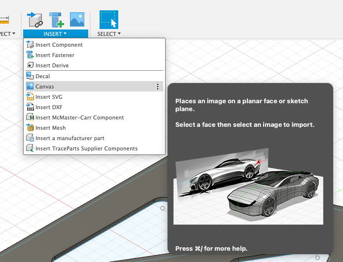
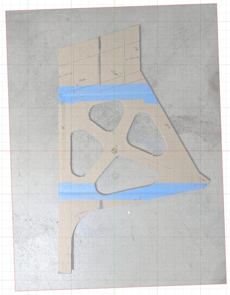
Users will want to find the canvas insert function and choose the picture they took of their cardboard template. Next, they will choose the face (in this case, the top of the 3D box) and then select the image. The image will be imported aligned with the X and Y coordinates along the borders of the picture. If reorientation is desired, it can be done before accepting the final position. The example image demonstrates a slightly rotated canvas.
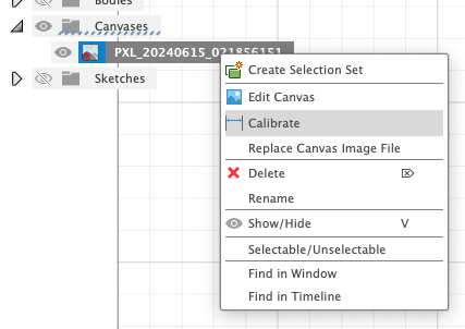
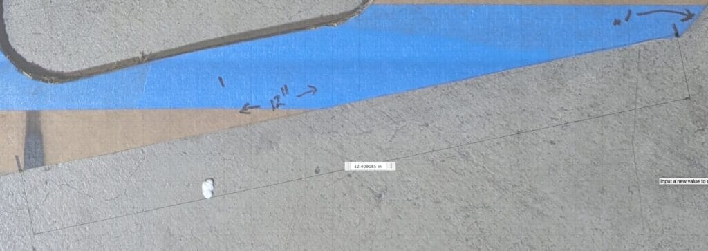
The most important part of this process is calibrating the image. Users should right-click on the canvas in the left-hand view menu and select the calibrate option. They can then select two points on the canvas and enter the length of that line in Autodesk Fusion. This is why it’s crucial to have carefully measured at least one length on the template during the prototyping phase. After inputting that measurement, all other lines drawn to trace the template outline will be accurate.
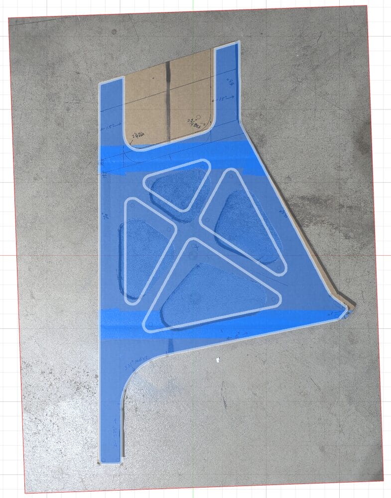
After calibration, users can simply utilize Autodesk Fusion’s sketching tools to trace the outline of the template. The sketch may not perfectly align with the imported template image. This discrepancy is often due to image parallax during import, or minor design adjustments. It can also be caused by constraints related to the chosen material and SendCutSend’s manufacturing specifications.
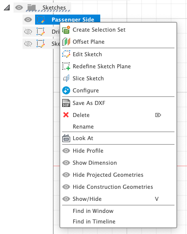
Congratulations! You are now ready to export the finished sketch to .DXF format. You’ll find the option by right clicking on the sketch and selecting “Save as DXF”
The file can then be uploaded to a SendCutSend account, initiating the processing and shipping order. A final suggestion: If unsure about the exact fit, wanting to double-check dimensions, or if this is a first-time experience with the process, SendCutSend offers inexpensive options like hardboard or chipboard. These materials are significantly more affordable than others and can be used to create test pieces. If the part is large, complex, or made of expensive materials, this approach helps ensure that investments are maximized when finalizing the design.
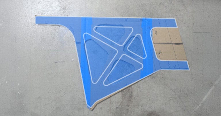
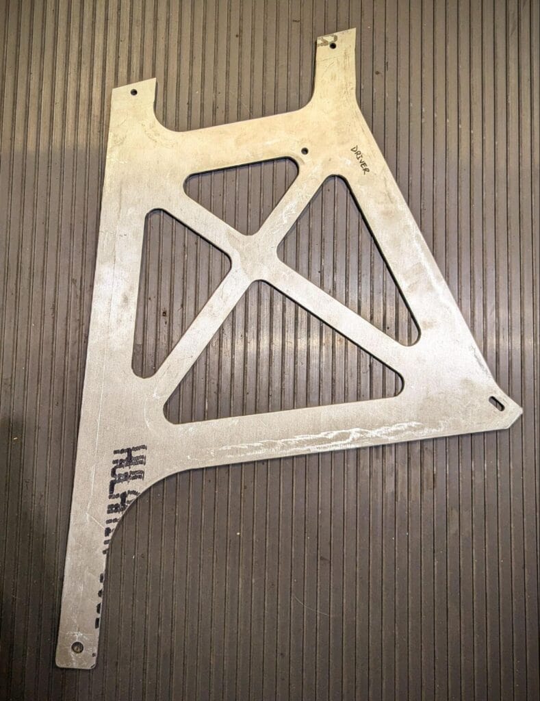
At the end of the process you’ll end up with exactly what you asked for, and that’s the great part. Below is the 6061-T6 part that was designed in this blog and shipped only a few days after I uploaded the .DXF. I’ve added the slots and mounting points after it arrived, but the quality and alignment was top notch. Good luck with your projects.
TLDR summary:
Here is a 6-point summary of the key steps involved in creating high-quality parts using cardboard templates and CAD software:
- Create a Precise Cardboard Template: The foundation of this process is a carefully crafted cardboard template. Use high-quality materials and tools, and ensure all measurements and angles are accurately recorded on the template.
- Consider Engineering Factors: Think about the forces the part will experience, the materials you’ll use, and any necessary design adjustments. Incorporate features like slots for adjustability if needed.
- Capture a High-Quality Photo: Take a clear, well-lit photo of your template against a neutral background. Position your phone directly overhead to minimize parallax.
- Import and Calibrate in CAD Software: Use the canvas function in your CAD software to import the photo. Calibrate the image using a known reference measurement from your template.
- Trace and Refine the Design: Utilize sketching tools to trace the template outline in the CAD software. Make any necessary adjustments based on material constraints or design refinements.
- Upload the DXF to SendCutSend: Consider using a less expensive material to double check fitment if the part is expensive. Have fun and be creative!


