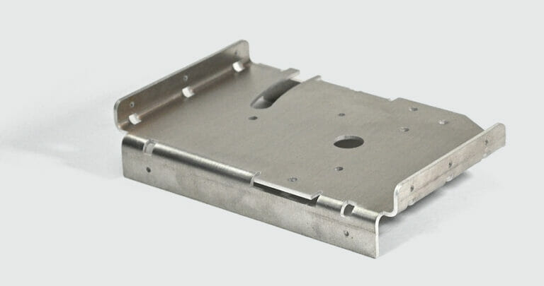
Laser cut sheet metal is a popular material in many industries due to its durability, strength, and versatility. At SendCutSend, we stock multiple high-quality materials and offer CNC bending services so your project is limited only by imagination (and a few pesky rules of physics). In this guide, we’ll discuss ways to accommodate those rules so you can avoid deformation in your bent sheet metal parts. Let’s get started!
Why does deformation occur?
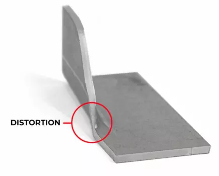
With regards to sheet metal bending, deformation is unintended distortion of cut features or flanges during bend operations.
This happens if
- Holes or other cut features are too close to bends
- Flanges are too short
- Flanges are poorly supported
- Flanges taper below the material’s minimum flange length
- Bends are not relieved
Fortunately, these issues are easy to prevent or work around by following SendCutSend’s bending design guidelines and best practices.
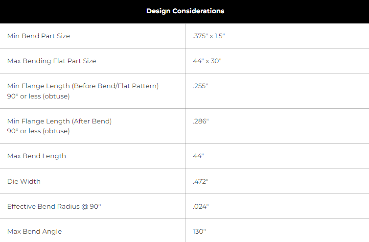
Using the Material Details
Avoiding deformation often requires referencing the manufacturing specifications for the material needed. Every sheet metal that SendCutSend offers is listed in the Materials Library, where you can find the individual material info page.
Just navigate to the info page and scroll down to find the Material Details. All critical specifications for each stock thickness will be available there under Design Considerations.
Commonly referenced specs are
- Die Width
- Minimum Flange Length
- Effective Bend Radius
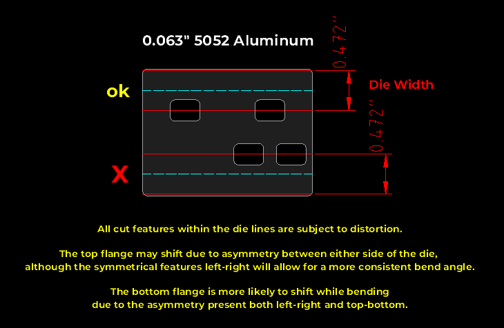
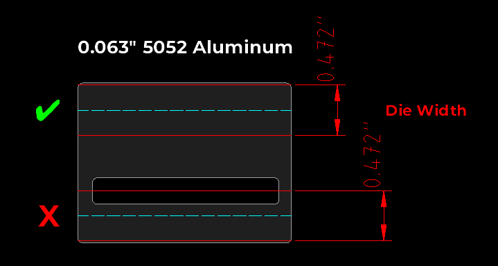
1. Mind the Die Lines
Keep all features at least half the full die width away from the center of each bend. Following this simple rule of thumb will prevent most feature distortion issues.
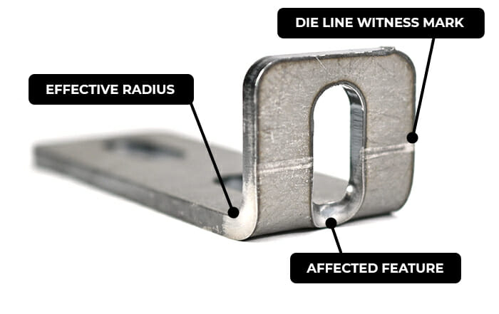
SendCutSend forms sheet metal via air bending (learn more about our process here). In a nutshell, we use a punch and die to bend flanges. When features fall directly within the bottom die area, they are liable to warp since that is where the material is actively bent.

For example, 0.104” mild steel is bent with a 0.630” die. Features within the distortion area will be affected.
To avoid this, move features outside the distortion area and/or move the bend location.


Take a look at our in-depth explanation about this here: Die Line Considerations
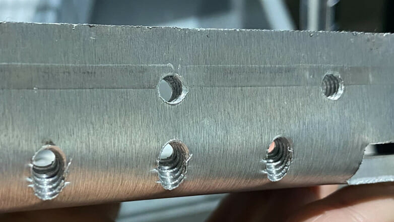
For tapped and countersunk holes, this is especially relevant since we bend parts after tapping and countersinking operations. Tapped and countersunk holes are likely to be unusable after warping so be sure to set these a sufficient distance away from the bend line.
For hardware insertion, holes must be at least the minimum distance from center of bend to center of hardware insertion hole (measured from flat pattern) in order for hardware to be installed successfully.
This information is available in the Material Details for hardware-eligible materials.
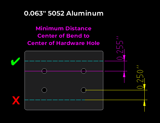
Wondering why hardware mount holes can fall within the die lines as long as they are at least the minimum distance away from the bend centerline? We allow this because when the hardware is inserted, the pressure applied to the hole will correct any die line deformation and enable successful hardware installation.
We have specific design guidance for parts with hole operations here.
2. Stick With Symmetry
Avoiding cutouts within the die lines is preferred if at all possible.
However, if it is impossible to eliminate cutouts within the area to be bent in your design, those cutouts should be symmetrical. This will allow for a more consistent bend angle across the flange.
Asymmetrical cutouts result in asymmetrical distribution of pressure when the punch presses into the material. In thinner materials this can result in parts that are bent out of tolerance, and in thicker materials this could present a safety hazard for brake operators.
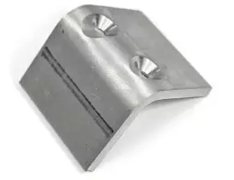
3. Include Enough Flange
Naturally, your design must have a flange if you require bending services. The flange is the edge you need bent.

When it comes to distortion, the question is whether the flange meets our minimum length requirement for the material across the entire bend.
You can find both the Min Flange Length (Before Bend/Flat Pattern) and Min Flange Length (After Bend) values in the Material Details.
- If you are working in a 2D program like QCAD to design your part, refer to the Min Flange Length (Before Bend/Flat Pattern) value to measure your flange length.
- If you’re designing in a 3D program like Autodesk Fusion, use the Min Flange Length (After Bend) value. This is also referred to as the finished overall dimension (OD) of the flange. Be sure to set up your sheet metal rules using our effective bend radii and bend deduction values. These specs can all be found in the Material Details and at the bottom of our bending calculator page.

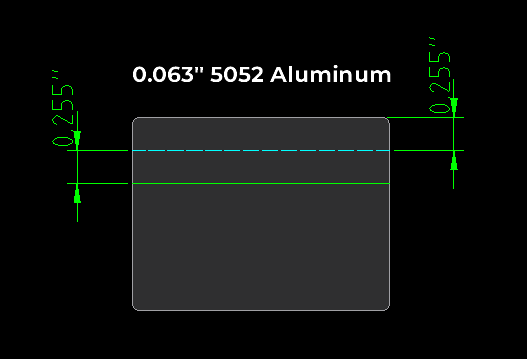
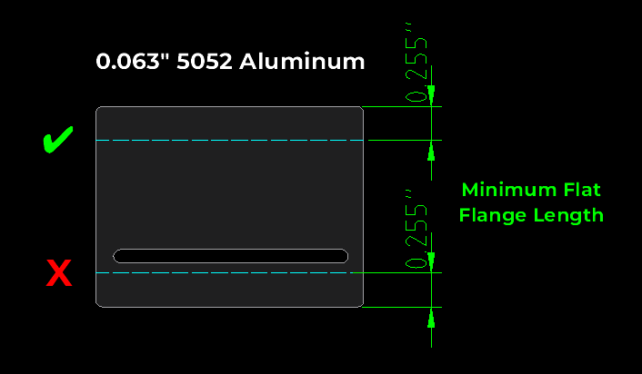
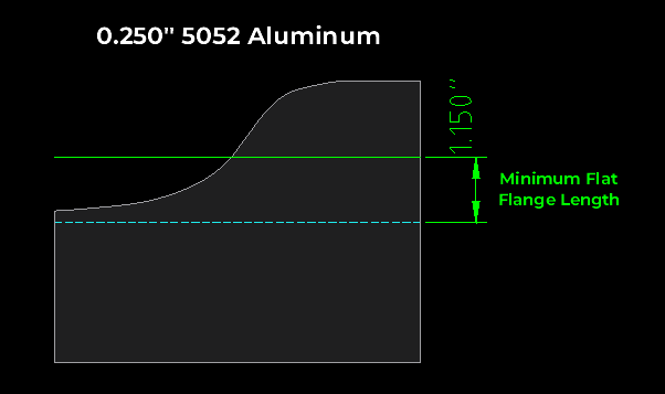
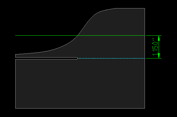
The minimum flat flange length value (before bending) dictates how much material we need on both sides of the bend line in order to perform the operation successfully.
For example, in 0.063” 5052 aluminum, the minimum flat flange length is 0.255”.
In this example, there is clearly sufficient material on both sides of the bend line.
4. Support Your Flanges
Flanges that technically meet the minimum length may lack adequate support, resulting in distortion. This is because for most materials, the minimum flat flange length should be met for approximately 50-60% of the bend’s length (length of the bend centerline). This ensures the flange is supported enough to be bent within SendCutSend’s established tolerances.
Thicker materials (especially 0.187” – 0.250”) require a higher proportion of the flange to meet the minimum due to safety and tolerance considerations.
In this example, while the bottom flange technically meets the minimum flat flange length, the flange is poorly supported since a large amount of material has been removed.
For an overview of flange contact points during the air bending process, check out our Guide to Planning Features Around Bend Lines.
This consideration also applies if large parts of the flange won’t make contact with either side of the die.
Simply put, an ideal flange provides the following:
- Adequate length to cover the bottom die and brace against the press brake’s backgauge
- Sufficient symmetrical material within the area to be bent, which allows the punch to apply pressure evenly.
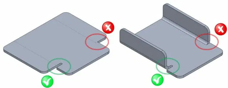
5. Relieve Tapered Flanges
Tapered flanges will distort if the taper dips below the minimum flat flange length for the chosen material. This is because there is not sufficient contact on the tooling to execute force upon the material and form the tapered area.
To avoid distortion, you can add a relief along the bend line up to the point where the minimum flat flange length is met.
We have more information about this here: Bending Deformation in Tapered Flanges
6. Give Bends Space or Add Reliefs
Every flange requires a certain amount of space in order to be formed without distorting the base of the part. This is mainly impacted by the effective bend radius of the material, which is the internal radius of the flange after it is formed. The effective bend radius for each material is listed under the Material Details.
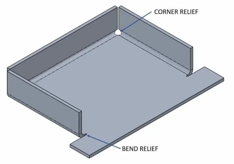
To provide the space needed for a bend to occur, you can either move a bend away from the base of a part, or you can add a relief slot, notch, or circle to prevent tearing.
For close box bends, corner reliefs are often necessary. Be sure to design box bends with adequate clearance as well so the flanges do not collide.
The thicker a material is, the more likely it is to require reliefs if there is not adequate space for a bend. Acute bends also benefit from reliefs more, while obtuse bends may be able to do without them.
We have a thorough, in-depth tutorial about this here: Guide to Designing Bend Reliefs
7. Follow Odd Flange Guidelines
If your design calls for an oddly shaped flange, we’ll need you to add a flat surface using break-off tabs in order to create a parallel edge to the bend line. We have specific guidance on how to do this here: Odd Flange Considerations
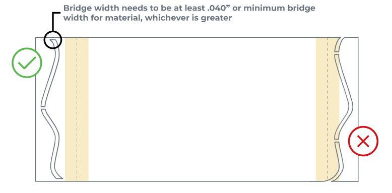
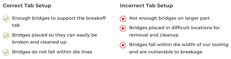
We’ll need your breakoff tab to be a sufficient length relative to your part’s overall flat length. Please note, we may request a longer tab if needed for a successful bend depending on your design’s geometry.
- 0-5 inch part: 0.500″ minimum breakoff tab
- 5-10 inch part: 1.000″ minimum breakoff tab
- 10+ inches: 1.500″ minimum breakoff tab
The breakoff tabs’ connecting bridges must not fall within the die lines. Tabs are vulnerable to breakage if the connecting bridges are within the die area.
Conclusion
With this guidance in hand, you now know how to avoid deformation in bent sheet metal parts!
To recap:
- Keep cut features at least ½ the die width away from the bend centerline
- If abiding by #1 is impossible, then ensure that any features within the die line are symmetrical
- Ensure the minimum flat flange length is met on both sides of the bend centerline
- Ensure the flange is well supported, ideally with solid material throughout the minimum flange length
- Relieve tapered flanges if the taper dips below the minimum flat flange length for the material
- Ensure all bends have adequate space or are relieved in order to prevent tearing
- Follow SendCutSend’s odd flange design guidelines
For more advice when designing for bending services, check out these resources:
- SendCutSend Bending FAQs
- Design Considerations When Planning Sheet Metal Bends
- Guide to Planning Features Around Bend Lines
- Preflighting Bent Sheet Metal Parts in QCAD
- 10 Common Reasons Your Design is Failing SendCutSend Preflight
Be sure to read through our complete Sheet Metal Bending and Forming Guidelines as well. Once your design is ready, upload it to our website for instant pricing. Happy bending!


