With our huge selection of high-quality materials and a wide range of available thicknesses, it can be overwhelming to pick the right size for your project. In this article, we’ll cover which properties of a material you should review when deciding on a thickness.
5 Mechanical Properties of Materials You Should Evaluate for Your Project
There are many reasons to select one thickness over another when designing your project. Even without knowing the mechanical engineering behind how the properties are measured, the mechanical properties of a material can help guide you to making the right selection.
1. Stiffness/Elasticity
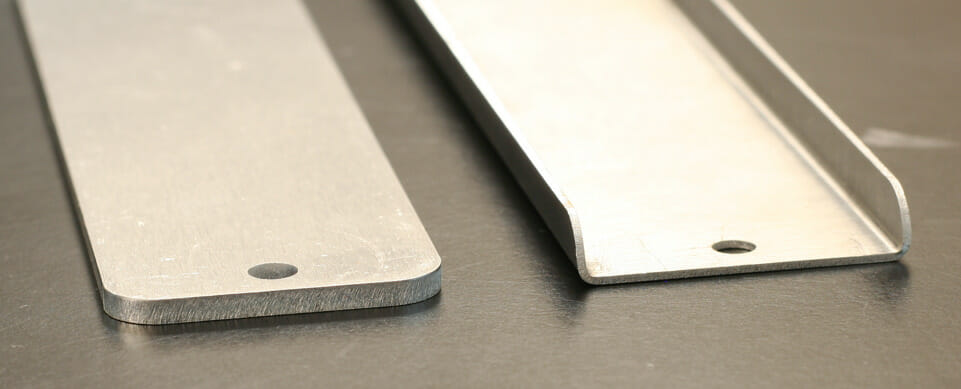
Stiffness is a measure of how much a part deflects or bends when a specific force is applied. Below the strength limits of a material, just about everything behaves like a spring. You can think of the stiffness of your parts as an effective spring rate: sometimes it’s desirable to have a part flex when force is applied and you want to control that rate and other times you want your part to be as stiff as possible to minimize how much it deflects under load. A material’s modulus of elasticity is a factor in part stiffness, but material thickness is another. It’s possible to design your parts from thinner materials, but have a higher stiffness by including features like bends.
Check out this article for more information on how bending can increase stiffness in your parts.
2. Strength
Strength is a measure of how much stress a part can see before it is either permanently deformed (bent, dented, etc.) or broken (cracked, fractured, split, etc.). Strength is a property of the material, and can be different depending on how the part is stressed/loaded. When you look up the strength of the material, you’ll commonly find a few different strengths listed corresponding to the ways the part can be stressed.
Tensile Strength
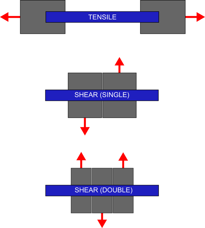
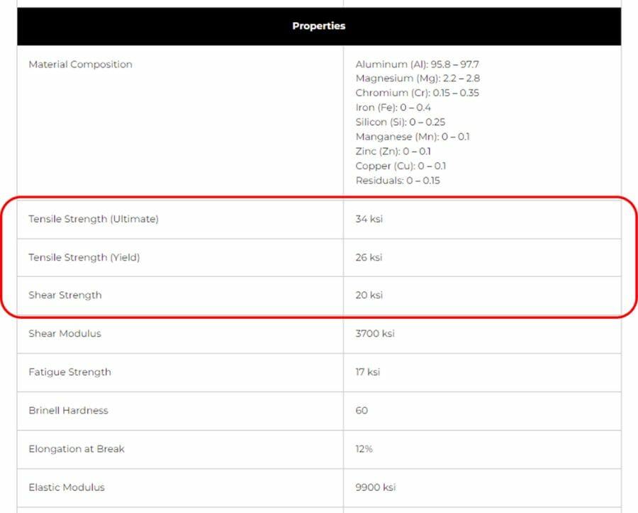
Tensile strength is used when the part is stretched or compressed (some materials may have a different strength in tension versus compression). When you’re looking at plastic deformation, that’s permanently deforming but not breaking, that’s called Yield Strength. When you’re looking at going past deforming the part all the way to breaking, that’s called Ultimate Strength.
Shear Strength
Shear strength is used when the part is being sheared. (Think of the two blades on a pair of scissors cutting paper. That’s shearing.) Shear can happen in any number planes at the same time. Generally, the more shear planes you can spread the force across, the less stress each individual plane will see.
Ultimate, yield, and shear strength are all mechanical properties of the material and can be looked up. We provide this info on our material pages.
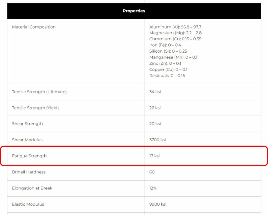
Fatigue Strength
The last type of strength we’ll discuss here is fatigue strength, also sometimes called endurance strength. Fatigue strength is generally less than the materials yield strength. It refers to the level of stress the material can safely see repeatedly without failure. Stresses above the fatigue strength but below the yield strength may be ok, but there are a limited number of times your parts can see that stress before they fail from fatigue. The further past the fatigue strength, the fewer the number of cycles before failure. If your parts never see stresses higher than the materials fatigue strength, it should be able to withstand an infinite number of cycles without fatiguing. As with the other strength properties, you can find fatigue strength listed on our material pages.
3. Ductility
Ductility or malleability is a way to quantify the amount of plastic deformation a material can handle before it breaks. Will it bend like a paper clip or snap like ceramics? Many alloys of steels are relatively ductile materials, but hardening a steel can often reduce ductility increasing its brittleness. Temperature can also affect a material’s ductility. Often high temperature will make a material more ductile, which is why many metals are formed using heat.
4. Fracture Toughness
All materials have microscopic imperfections, small cracks and voids both internally and on their surfaces. Fracture toughness is a measure of the ability of a material to handle forces and stresses without those small imperfections spreading to become large imperfections and causing the material to break. Both ductility and fracture toughness are important properties to evaluate in making blades, whether that’s a kitchen knife, ax head or lawnmower blade.
5. Wear Resistance
Parts that come in contact with each other will cause abrasion. How much depends on the materials, contact forces and even speed and frequency of contact. Harder materials tend to cause more wear on softer materials. A material’s abrasion resistance can be important for selecting the right material. Select a material that is too thin and you may have issues with it wearing through.
6. Corrosion
Corrosion tends to be an afterthought for a lot of parts. Selecting the right material for the environment can often be enough to eliminate corrosion problems. Stainless steel and aluminum withstand exterior weather well on their own, but typical steels need to be coated. A protective finish, like paint or powder coating, can also extend the life of your parts. Sometimes, however, corrosion can’t be prevented. When it’s inevitable, selecting a thicker material can buy your parts more time in service before they’re corroded enough to need replacing.
9 Additional Considerations to Assess Material Thickness
Some aspects of your design don’t correlate directly to a single material property, but they can be a major influence on which thickness to choose.
1. Safety
It’s typically good practice to design your parts with some factor of safety, meaning your parts are designed to be able to carry loads higher than what they’ll actually see in use. A bracket strong enough to support a 500 lb weight that will only ever see a maximum of 250 lb has a safety factor of 2.
2. Orientation
Not all materials behave uniformly in all directions. Most metals like aluminum, steel, stainless, copper, brass, titanium, etc. will behave the same way no matter which way they are oriented. The same is not necessarily true for materials like plywood, certain plastics and carbon fiber. Those materials can have different mechanical properties in one direction versus another because of the way they are constructed.
3. Buckling
Buckling is an issue with long, thin parts loaded in compression. The material may be plenty strong, but due to minor irregularities in physical parts, long thin parts will start to bend to one side and will no longer be able to support the load without collapsing. You can see this effect when you stand a flat metal ruler up on end and push down. It’ll buckle and start to bow out to one side. Similar to beam formulas, there are simple column buckling formulas you can look up and use to be sure your part won’t have buckling issues. Some of the methods we discussed to increase stiffness can also be applied to improving buckling. Increasing thickness, reducing length, and adding bends or other shapes like dimpled holes can all reduce the point at which your part buckles.

4. Weight
Weight is a function of material density and the amount of material in your part. Aircraft parts, race car parts, drone parts, and even parts meant to be carried like camping gear are all likely to be designed to minimize weight. It should be obvious that reducing the thickness of your part will also reduce its weight and vice versa. When weight reduction is a primary driver for your design, you’ll typically reduce weight until strength or stiffness become limiting factors. For some designs, you’ll want to control how weight is distributed over your part. Maybe your design needs to be balanced or you want additional weight at the bottom for stability. By selecting thicker and thinner materials strategically, you can fine tune those aspects of your design.
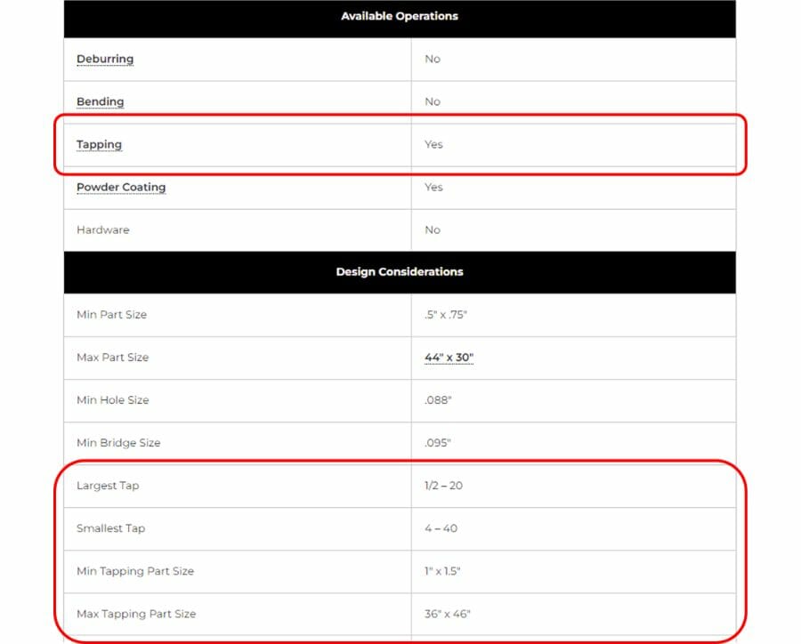
5. Tapping
We included tapping here because it can often be overlooked when choosing a material thickness. Whether you’re tapping your own holes or having us do it for you, you’ll want to pay attention to material thickness. The materials page for each of the materials we offer shows both whether or not the material is suitable for tapping, as well as the maximum and minimum recommended tap size. This differs by material thickness, so if the thread size you need doesn’t fall within the recommended range, try moving up in thickness. If you know your threads will see higher forces, you may want to aim higher than the minimum thickness to ensure you have enough threads to carry the load.
6. Fine Details
Laser cutting is a great way to get fine detail cut into your parts much easier and cleaner than would be practical by hand. But even with laser cutting, there are limits to the details that can be cut cleanly. In general, the thinner the material, the easier it is to cut small details without issues. As material thickness goes up, so should the size of the cutouts in your parts. We use the general rule that interior cuts shouldn’t be smaller than about 50% of the material thickness. You can read more about this in our laser cutting guidelines.
Similarly, if you’re having your parts bent, material thickness will be a factor in the bend radius. Typically thicker materials have larger bend radii. If you need to put a hole close to a bend, you may want to consider the size of the bend radius.
7. Part Size
Some material thicknesses are not available in all sizes. Generally, thicker material isn’t as easy to make small parts from due to removing it from the surrounding material. Maximum part size is not usually limited by material thickness but is more a limitation of handling and shipping. Keep in mind that oversized parts made of thin material will be more flexible and prone to deformation.
8. Welding
With the right equipment and skills, any thickness of metal can be welded. If you’re a beginner welder, you’ll probably find it easier to weld thicker materials as thinner materials are easier to burn through. Welding different thicknesses together can also be a little more challenging for new welders. Thicker materials require extra heat while thinner materials may melt through. On the other hand, welding thicker materials ¼ inch and up might require a machine with some more power. If you’re just starting out welding or you’re limited to a smaller machine, material thickness might be something you’ll want to consider for your design.
9. Aesthetics
The last topic we want to discuss here is arguably subjective, but choosing the right material thickness for your parts can play a huge role in getting the right look. For purely functional parts, like brackets and braces, they’re mostly driven by factors like strength, stiffness, weight, etc., with appearance further down on the priority list. But some parts are driven almost entirely by aesthetics. If you’re designing signs or decorative parts, you will want to pick your material thickness to get the look you need.
Choosing the Right Material for Your Project
When choosing the right thickness for your parts, there are many factors to consider. Structural parts like brackets and braces may be driven by strength and stiffness. Sometimes minimizing weight while maintaining strength and stiffness is important. When you need to have tapped holes in your part, thread size may push you to a minimum material thickness.
Some materials are available in a wider variety of thicknesses than others with a few materials only available in a single thickness. When selecting your material, a specific thickness availability may drive you to use one material over another.
In the end, sometimes a single factor drives the decision, sometimes it’s a combination of many factors, and the final choice is a compromise between performance, ease of use, and looks. Visit our materials page to get more details on each of the materials we offer to help you with your next project. Once you’ve selected your material and thickness, upload your design for instant quoting!


