Laser cutting is perfect for complex projects that require precision, but there are a few key design considerations you will want to keep in mind to ensure the perfect result. Designing a part properly for laser cutting will also help cut down any manufacturing questions, which can be important if you are on a tight timeline.
Using proper geometry in your laser cutting project will ensure your design translates into reality in the way that you intended. Without taking steps in the design process to ensure that minimum geometry requirements are met, your part may not be cut accurately or have the structural integrity that you intend. There’s no greater frustration than needing to remake a crucial part due to a simple error, and we’re here to help you avoid that!
Optimizing Your Design for Laser Cutting
By ensuring that your design is ready for production, you can save precious time and ensure the final product is exactly what you need. Thankfully, it isn’t difficult to optimize your design.
Before submitting your project, check for these common design issues:
Incorrect file setup
Your file should be two-dimensional in vector format. All objects should be on the same layer, and all stray points, duplicate lines, empty objects, etc. have been removed. Don’t forget to check for any accidentally intersecting lines as well. As a guideline, it’s best to use inch-units with the file at a 1:1 scale.
Broken contours and intersecting lines
If shapes aren’t fully connected end to end, the laser won’t be able to follow the path in the way that you intend. By reviewing your file in Outline mode in your chosen design software, these missed areas become more evident. Check out the suggestions here for a more in-depth explanation on open contours and how to fix them. You should also check that all shapes are merged or combined before submitting.

Pre-nested files
Pre-nested files contain more than one unit, and can have multiple of the same part or a variety of small parts. We recommend against pre-nesting files that contain multiple of the same part because it’s more budget-friendly and better for the laser cutting process if you upload a file that contains only one part, and then adjust quantities during checkout. If you have multiple different designs and only want a small quantity of each, pre-nesting those designs in one file is completely fine and we’ll take care of the rest.
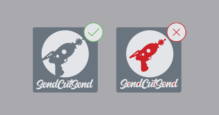
Unconverted text and type
Your text should be converted to outlines or paths, and all negative shapes should be removed. Text that is not converted to outlines or paths will not be processed by our automated system and will result in a rejection of your file. Any text that is cut out should be properly stencilized with bridges. For other advice on ensuring your text is fully prepared for laser cutting, check out our other blog posts for adjusting text.
Kerf compensation
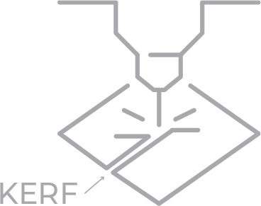
If you’ve designed for laser cutting before, you may be familiar with the term “kerf” or learned to compensate for this factor in your design. Kerf is the additional material burned away by the laser when cutting, and the kerf width is dependent on the type of laser, the type and thickness of material used, as well as several other project elements. These variables in the parts being cut make it difficult to calculate and then compensate for kerf in your design. Kerf can be especially difficult to design around when dealing with small, intricate items.
Our proprietary laser cutting and waterjet cutting services will automatically compensate for beam width and kerf in your part file, so if you compensate for it yourself before sending it to us, you’ll end up with a part that is likely outside your tolerances. So be sure to send us the file with the part designed with the exact dimensions you need, and we’ll adjust for kerf on our end.
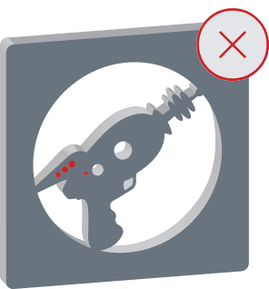
The Importance of “Bridging”
“Bridging” is the process of designing geometry without any loose shapes floating in your design. Cutting letters or designs with counters, i.e. holes in the middle of a letter, will create a void once the material is cut out, causing the inner geometry and core of the design to be lost in the machining process.

Bridges connect the holes in letters to the outer shape, such as the letter R, to make sure the void has a connection to the outside of your design. Think of a stencil: each letter with a hole has a small line connecting it to make sure the letter (or design) retains its intended shape. Since bridging can be tedious, try using a font that is already in stencilized or bridged format. If you’re using a program such as Adobe Illustrator, many stencilized fonts will be available to you as part of the software package. If you’re utilizing a font you’ve downloaded via an external source, make sure the source is trusted and you are able to convert the text to paths in your design software.
If your design doesn’t have text but has multiple pieces of inner geometry, make sure that you have added bridging or adjusted the design to ensure that nothing is lost during cutting.
For examples in bridging and optimizing your text, check out this handy video guide with step-by-step instructions.
Sizing Guidelines to Keep in Mind
Laser cutting is a great multi-purpose manufacturing method, but there are a few sizing guidelines and constraints you should follow to ensure success every time.
Make sure your internal geometry isn’t too small
The minimum internal geometry size for laser cut parts changes depending upon your chosen material and its thickness. No geometry should ever be smaller than .015”, but always check your design against the Minimums and Maximums charts for your material.
When laser cutting, any holes or cuts are 50% of your material thickness or greater. The laser creates multiple pierce points in a design, one for each time it must restart cutting, so there needs to be a minimum thickness of material to allow for the laser’s diameter.
Make sure the external dimensions fit within our guidelines
We offer a wide variety of materials with applications in everything from prototyping to precision robotics. The number of different materials we offer is one of our greatest strengths here at SendCutSend, but keep in mind that each material will have a different suggested minimum overall part size due to the differences in thickness and properties.
It’s once again vital to check our Material Minimum and Maximum Sizes guideline as you design your parts to ensure that smaller items can be cut from the thickness of material that you prefer.
Upload and Get An Instant Quote!
Once you have walked through these steps to optimize your design for laser cutting, you’re ready to get started with SendCutSend. If your file fits our guidelines, go ahead and upload your parts to our instant pricing tool. We produce most standard orders within just 2-4 business days of when you place your order.
If you’ve got any further questions about our design guidelines or file setup, check out our blog with dozens of educational resources to help you produce the best laser cut parts possible.


